TEACL-PIC-HV Flexipanel, TEACL-PIC-HV Datasheet - Page 3
TEACL-PIC-HV
Manufacturer Part Number
TEACL-PIC-HV
Description
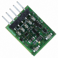
PROGRAMMER TEACLIPPER/PIC HI/LOW
Manufacturer
Flexipanel
Series
TEAclipper™r
Type
ISP (In-System Reprogramming)r
Datasheet
1.TEACL-USB.pdf
(8 pages)
Specifications of TEACL-PIC-HV
Contents
Programmer Board
Positions/sockets
1
For Use With/related Products
PIC Micro® 10F and 18F MCUs
For Use With
658-1026-5 - ADAPTER USB TEACLIPPER658-1025-5 - BOARD EVAL TEACLIPPER658-1024-5 - ADAPTER DEBUG TEACLIPPER/STAMP658-1023-5 - ADAPTER DEBUG TEACLIPPER/PICICD2
Lead Free Status / RoHS Status
Lead free / RoHS Compliant
Other names
658-1019-5


Preserve / Authenticate of code protected ROM is not
possible.
Override High Voltage Defaults:
Voltage Programming section below.
Embed Settings:
another user opens the file, it will default to the settings
selected.
HexWax Explorer may also be used to determine the
payload currently resident on a TEAclipper. When you
insert it into TEAclipper USB,
display information about the resident firmware. Press
the Details… button for more information.
Refer to the HexWax Explorer HW050 data sheet for
more information about the software.
Note: High Voltage TEAclipper/PICs with the marking
TCPr3 need a few moments to discharge in order to
reset properly. After loading the firmware onto the PIC,
you may need to remove it for about 5 seconds and
then re-insert it.
Programming PICs
To discharge the payload data into a PIC, connection
must be made as detailed in the Pinout Table. A PCB
header or series of plate-though holes is usually
provided on a target PCB for programming. Payloads
can be set for limited discharge, in which case they can
only program a limited number of PICs.
The TEAclipper has a limited life due to the low-cost
nature of the flash memory used. It can be reloaded
with firmware a maximum of 100 times. In addition, if
the limited-download or serialization features are used,
the total maximum number of downloads is 1600.
Evaluation and Development Guide
To experiment with TEAclippers, try downloading the
Eval1 and Eval2 firmware files from www.hexwax.com.
They don’t do much – flash LEDs once and twice
respectively on P0 and P1 – but they are enough for you
to become familiar with how TEAclippers are used.
You’ll find them by visiting the Products section of the
web site and downloading the PICeval pack.
A TEAclipper Evaluation Board is available. It includes
zero-insertion-force test sockets which may be useful for
programming a large quantity of PICs
The TEAclipper/PIC Debugging adapter is available
which
Page 3
Red & Grn on
continuously
Red & Grn flash
every 2s
Alternate Red & Grn
Occulting Green
2 Red flashes
3 Red flashes
4 Red flashes
5 Red flashes
6 Red flashes
8 Red flashes
13-Jan-08
translates
Red & Green LED Indicator Guide
Writes settings to hex file so if
the
Initializing
Connected to HexWax Explorer
Programming PIC
Programming complete
PIC not found
Authenticate failure
Erase limit reached
Limited discharge limit reached
No payload to discharge
Program verify failure
TEAclipper
TEAclipper//PIC DS508-6
HexWax Explorer will
Refer to High
programming
© FlexiPanel Ltd
connections to an RJ11 socket. This is designed for
development and debugging of applications using the
Microchip ICD2 In-Circuit Debugger.
Pinout Table
Specifications
Mechanical Drawing
Target Board Design Guide
When designing a PCB to facilitate frequent in-circuit
programming of PICs, a five pin 0.1” header socket
should be provided.
necessary to devise an adapter cable.
If it is anticipated that the board will only need to be
programmed once or twice in its lifetime, and the PIC is
small enough that the programming duration is quite
short, leaning the TEAclipper against five plate-through
holes will be sufficient.
Pin
Voltage on Vdd
Current, low voltage programming
Current, high voltage programming
Maximum erase cycles
Maximum high volt current I
1
2
3
4
5
†
Refer to Compatibility Chart for Vmin and Vmax values
Vpp/NMCLR
Name
PGD
PGC
Vdd
Vss
†
Refer to Compatibility Chart for Vmin values
Patents pending
Description
Power input Vmin – 5.5V DC
Program data (Bidirectional)
Program clock (Output)
Programming voltage / reset (Output )
Power Ground reference
For compact PCBs, it may be
Vpp
Vmin – Vmax DC
10mA max
80mA max
100
1mA
www.FlexiPanel.com
†
†
Related parts for TEACL-PIC-HV
Image
Part Number
Description
Manufacturer
Datasheet
Request
R

Part Number:
Description:
ADAPTER USB TEACLIPPER
Manufacturer:
Flexipanel
Datasheet:

Part Number:
Description:
ADAPTER DEBUG TEACLIPPER/PICICD2
Manufacturer:
Flexipanel
Datasheet:

Part Number:
Description:
ADAPTER DEBUG TEACLIPPER/STAMP
Manufacturer:
Flexipanel
Datasheet:

Part Number:
Description:
PROGRAMMER TEACLIPPER/PIC LOW-V
Manufacturer:
Flexipanel
Datasheet:

Part Number:
Description:
PROGRAMMER TEACLIPPER/STAMP
Manufacturer:
Flexipanel
Datasheet:

Part Number:
Description:
BOARD EVAL TEACLIPPER
Manufacturer:
Flexipanel
Datasheet:


Part Number:
Description:
IC USB ASYNC SRL UART 20-SSOP
Manufacturer:
Flexipanel
Datasheet:

Part Number:
Description:
IC USB SYNC SRL SPI 20-SSOP
Manufacturer:
Flexipanel
Datasheet:

Part Number:
Description:
IC USB SYNC SRL I2C 20-SSOP
Manufacturer:
Flexipanel
Datasheet:

Part Number:
Description:
IC USB ASYNC SRL UART 28-DIL
Manufacturer:
Flexipanel
Datasheet:

Part Number:
Description:
IC USB SYNC SRL I2C 28-DIL
Manufacturer:
Flexipanel
Datasheet:

Part Number:
Description:
IC USB SYNC SRL SPI 28-DIL
Manufacturer:
Flexipanel
Datasheet:

Part Number:
Description:
IC ENCRYPT KEY
Manufacturer:
Flexipanel
Datasheet:

Part Number:
Description:
IC ENCRYPT KEY 28-SSOP
Manufacturer:
Flexipanel
Datasheet: