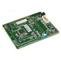
R0K33062PS001BE Renesas Electronics America, R0K33062PS001BE Datasheet - Page 4

R0K33062PS001BE
Manufacturer Part Number
R0K33062PS001BE
Description
R0K33062P STARTER KIT
Manufacturer
Renesas Electronics America
Series
Renesas Starter Kits (RSK)r
Type
MCUr
Specifications of R0K33062PS001BE
Contents
CPU Board, LCD Display Module, E8 Emulator, Cable, QuickStart Guide and CD-ROM
Silicon Manufacturer
Renesas
Features
Coding And Debugging, E8A Emulator, RS232 Serial Connection
Kit Contents
Board
Silicon Family Name
M16C/62P
Silicon Core Number
M30626FJPGP
Lead Free Status / RoHS Status
Lead free / RoHS Compliant
For Use With/related Products
M16C/62P
Lead Free Status / Rohs Status
Compliant
Other names
Q4300694
Table of Contents
Chapter 1. Preface ..................................................................................................................................................1
Chapter 2. Purpose .................................................................................................................................................2
Chapter 3. Power Supply ........................................................................................................................................3
Chapter 4. Board Layout .........................................................................................................................................4
Chapter 5. Block Diagram .......................................................................................................................................6
Chapter 6. User Circuitry.........................................................................................................................................7
Chapter 7. Modes..................................................................................................................................................14
Chapter 8. Programming Methods........................................................................................................................15
Chapter 9. Headers...............................................................................................................................................16
Chapter 10. Code Development ...........................................................................................................................21
Chapter 11. Component Placement ......................................................................................................................23
Chapter 12. Additional Information........................................................................................................................24
3.1. Requirements ...............................................................................................................................................3
3.2. Power – Up Behaviour .................................................................................................................................3
4.1. Component Layout .......................................................................................................................................4
4.2. Board Dimensions ........................................................................................................................................5
6.1. Switches .......................................................................................................................................................7
6.2. LEDs.............................................................................................................................................................7
6.3. Potentiometer ...............................................................................................................................................7
6.4. Serial port .....................................................................................................................................................8
6.5. LCD Module..................................................................................................................................................8
6.6. Option Links..................................................................................................................................................9
6.7. Oscillator Sources ......................................................................................................................................12
6.8. Reset Circuit ...............................................................................................................................................12
7.1. Boot mode ..................................................................................................................................................14
7.2. Single chip mode ........................................................................................................................................14
9.1. Microcontroller Headers .............................................................................................................................16
9.2. Application Headers ...................................................................................................................................18
10.1. Overview...................................................................................................................................................21
10.2. Mode Support ...........................................................................................................................................21
10.3. Breakpoint Support...................................................................................................................................21
10.4. Memory Map.............................................................................................................................................22
ii


