DEMO9S08EL32AUTO Freescale Semiconductor, DEMO9S08EL32AUTO Datasheet
DEMO9S08EL32AUTO
Specifications of DEMO9S08EL32AUTO


Related parts for DEMO9S08EL32AUTO

DEMO9S08EL32AUTO Summary of contents
Page 1
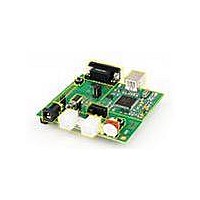
DEMO9S08EL32 Demonstration Board for Freescale MC9S08SE8 Microcontroller USER GUIDE Email: Support: support@axman.com www.axman.com ...
Page 2
CAUTIONARY NOTES ..............................................................................................................4 TERMINOLOGY.........................................................................................................................4 FEATURES ................................................................................................................................5 REFERENCES ...........................................................................................................................6 GETTING STARTED..................................................................................................................6 MEMORY MAP ..........................................................................................................................6 SOFTWARE DEVELOPMENT...................................................................................................6 DEVELOPMENT SUPPORT ......................................................................................................7 INTEGRATED BDM .............................................................................................................. 7 BDM_PORT HEADER........................................................................................................... 7 POWER ......................................................................................................................................7 POWER SELECT .................................................................................................................. 8 ...
Page 3
Figure 1: BDM_PORT Header....................................................................................................7 Figure 2: PWR_SEL Option Header ...........................................................................................8 Figure 3: VX_EN Option Header ................................................................................................9 Figure 4: COM ...
Page 4
CAUTIONARY NOTES 1) Electrostatic Discharge (ESD) prevention measures should be used when handling this product. ESD damage is not a warranty repair item. 2) Axiom Manufacturing does not assume any liability ...
Page 5
FEATURES The DEMO9S08EL32 is a demonstration board for the MC9S08EL32 microcontroller. Application development is quick and easy with the ...
Page 6
REFERENCES Reference documents are provided on the support CD in Acrobat Reader format. DEMO9S08EL32_UG.pdf DEMO9S08EL32_QSG.pdf DEMO9S08EL32 _SCH_A.pdf DEMO9S08EL32_Silk_A.pdf EL32DEMO.zip ...
Page 7
DEVELOPMENT SUPPORT Application development and debug for the target MC9S08EL32 is supported through a background debug mode (BDM) interface. The BDM interface consists of an integrated USB BDM and a 6-pin ...
Page 8
During application development, the board may be powered from either the USB-BDM or the PWR connector. To utilize LIN ...
Page 9
powered from the PWR connector, the integrated BDM may still be used to develop and debug application code. ...
Page 10
TIMING The DEMO9S08EL32 is configured to use the target MCU’s internal clock source by default. Space is provided for ...
Page 11
LIN Communications The DEMO9S08EL32 applies a fault tolerant, Local Interconnect Interface (LIN) physical layer (PHY) for use in developing automotive control applications. The PHY supports LIN bus functionality for input voltages ...
Page 12
Figure 7: COM_SEL Option COM LIN Select LIN communications COM LIN Select COM communications USER I/O User I/O includes ...
Page 13
Temperature Sensor A surface-mount, NTC Thermistor is installed at location RZ1. This component provides a voltage input to the ...
Page 14
MCU I/O PORT The MCU I/O PORT connectors (J1 and J2) provide access to the MC9S08EL32 I/O signals. Figure 9 below show the pin-out for each MCU I/O connector. Figure 9: ...