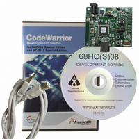
DEMO9S08QD4 Freescale Semiconductor, DEMO9S08QD4 Datasheet - Page 8

DEMO9S08QD4
Manufacturer Part Number
DEMO9S08QD4
Description
BOARD DEMO FOR MC9S08QD FAMILY
Manufacturer
Freescale Semiconductor
Type
MCUr
Specifications of DEMO9S08QD4
Contents
Board, Cable, CD
Processor To Be Evaluated
MC9S08QD
Data Bus Width
8 bit
Interface Type
USB
Silicon Manufacturer
Freescale
Core Architecture
HCS08
Core Sub-architecture
HCS08
Silicon Core Number
MC9S08
Silicon Family Name
S08QD
Rohs Compliant
Yes
For Use With/related Products
MC9S08QD2, MC9S08QD4
Lead Free Status / RoHS Status
Lead free / RoHS Compliant
Describing the Code
To see how to move a stepper motor applying voltages to its coils see
synchronized signals moves the motor step by step while coil A and coil B are driven at different moments.
When working with input voltages, frequency is similar to voltage reference height (VREFH) and the duty
cycle is similiar to voltage variations measured in the ADC.
4
The code is based on the state machine diagram in
constants and global variables are mentioned in this process. Constants are used to generalize the code and
make changes faster. Variables are used to make specific calculations while the code is running and getting
data from the ADC. They also track program stages.
Below are the constants and variables declared in the code:
/* Global constants */
#define SWITCH_ON
#define START_POSITION
#define CHECKED
#define NOT_CHECKED
#define Idle_DONE
/* Global variables */
unsigned int
unsigned int
unsigned int
unsigned int
unsigned int
unsigned int
unsigned int
unsigned int
To help you understand the process below, there is a state diagram that represents the main loop of the
system. See
8
1. Initialization
2. Check mode
3. If (Required_position == Current_position)
Describing the Code
Figure
Bus
Frequency
Driving a Stepper Motor Based on the MC9S08QD4 and Other 8-bit Families, Rev. 0
Coil A1
Coil A2
Coil B1
Coil B2
Current_position;
Required_Position;
Frequency;
Duty_Cycle;
Duty_Cycle_100;
Duty_Cycle_H;
Check;
SWITCH, i;
10:
0x0A 0x06 0x05 0x09 0x0A 0x06 0x05 0x09
1
1
0
0
Cycle
1
0
0
1
n
5000
0
1
0
0
1
0
1
100
0
1
1
0
Figure 9. Port A Outputs
/* To know if the frequency and duty cycle been checked */
/* Since it is limited to 100 degrees */
/* To know if the frequency and duty cycle been checked */
/* To know if the frequency and duty cycle been checked */
/* To know the steps to be in the first position */
/* Used to know the new position of the stepper */
/* Used to know the frequency of the PWM */
/* Used to know the duty cycle of the PWM */
/* Used to know the duty cycle of the PWM */
/* Used to know the duty cycle of the PWM */
/* Used to know the process status */
/* general use variable */
/* Used to know the previous position of the stepper */
Figure
10. Four main processes are described. Global
Figure
4. The process of
Freescale Semiconductor


