DEMO9RS08KA8 Freescale Semiconductor, DEMO9RS08KA8 Datasheet
DEMO9RS08KA8
Specifications of DEMO9RS08KA8


Related parts for DEMO9RS08KA8

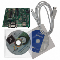
DEMO9RS08KA8 Summary of contents
Page 1
... DEMO9RS08KA8 Demonstration Board for Freescale MC9RS08KA8 User’s Manual ...
Page 2
...
Page 3
... DEMO9RS08KA8 Demonstration Board for Freescale MC9RS08KA8 (20-Pin DIP) User’s Manual Revision 1.1 Copyright © 2007 SofTec Microsystems DC01491 ® ...
Page 4
... THEREOF. Trademarks SofTec Microsystems is a registered trademark of SofTec Microsystems. Freescale™ and the Freescale logo are trademarks of Freescale Semiconductor, Inc. Microsoft and Windows are trademarks or registered trademarks of Microsoft Corporation registered trademark of International Business Machines Corporation. Other products and company names listed are trademarks or trade names of their respective companies. ...
Page 5
Contents 1 Introduction 5 1.1 Overview 5 1.2 Package Contents 5 1.3 Supported Devices 5 1.4 Recommended Reading 5 2 Hardware Features 7 2.1 Demonstration Board Features 7 3 Software Setup 9 3.1 Overview 9 3.2 Host System Requirements 9 ...
Page 6
...
Page 7
... The DEMO9RS08KA8 Demonstration board has been designed for the evaluation, demonstration and the debugging of the Freescale MC9RS08KA8 microcontroller. The DEMO9RS08KA8 can be used as a standalone application, or via its built-in USB-to-BDM bridge, or together the Freescale Student Learning Kit (Freescale code: MCUSLK) through an external 36-pin I/O female header connector. ...
Page 8
Page 6 ...
Page 9
... Hardware Features 2.1 Demonstration Board Features The DEMO9RS08KA8 board features: A MC9RS08KA8 microcontroller (in 20-Pin DIP package, already programmed with a demo application); A provision for a low-frequency crystal power supply input connector; Power input selection jumper for selecting the input voltage source input connector; o USB connector. ...
Page 10
... Page 8 The DEMO9RS08KA8 Demonstration Board ...
Page 11
Software Setup 3.1 Overview Note: before connecting the Demonstration Board to the PC recommended that you install all of the required software first (see below), so that the appropriate USB driver will be automatically found by ...
Page 12
... CodeWarrior installation path. 4. Click on the “Copy examples for CW08 V6.1” option. An Explorer window will open. Copy the “DEMO9RS08KA8” folder to your PC location of your choice. These are the examples specific for the demonstration board, and will be used later in the step-by- step tutorial. ...
Page 13
Hardware Setup 4.1 First Connection The Demonstration Board connects to a host PC through a USB port. Connection steps are listed below in the recommended flow order: 1. Install all the required system software as described in the previous ...
Page 14
Click the “Next >” button. 7. Depending on your Windows settings, the following warning may appear. Note: this warning is related to the fact that the USB driver used by i the Demonstration Board is not digitally signed by Microsoft, ...
Page 15
Click the “Finish” button to exit from the “Found New Hardware Wizard” procedure. 9. The Demonstration Board’s USB driver is now installed on your system. 4.2 Power Supply The Demonstration Board can be powered in three ways ...
Page 16
...
Page 17
Operating Modes 5.1 Overview The Demonstration Board can work in two modes: “standalone” mode and “host” mode. 5.2 Standalone Mode In standalone mode connection is required. The microcontroller is factory programmed with a sample application. To run ...
Page 18
Note: all MCUs in the RS08 family contain a single-wire background i debug interface which supports in-circuit programming of on-chip non- volatile memory. This system does not interfere with normal application resources. It does not use any user memory or ...
Page 19
... Start CodeWarrior by selecting it in the Windows Start menu. 4. From the CodeWarrior main menu, choose “File > Open” and choose the “DEMO9RS08KA8\C\Demo\Demo.mcp” file. This is the board example you copied from the SofTec Microsystems “System Software” CD-ROM. 5. Click “Open”. The Project window will open. ...
Page 20
...
Page 21
Summary of Jumper and Connector Settings 7.1 Jumpers Name Reference J102 1 PTB6 PTB7 PTC0 PTC1 PTA0 PTA1 PTA2 PTA3 PTA5 J302 1 BKGD RESET# J402 J403 1 PTB0 (RX) PTB1 (TX) Description/Pinout I/O ENABLE Installed: ...
Page 22
Connectors Name Reference J101 ...
Page 23
Name Reference J103 J301 J401 2 1 J404 Description/Pinout BDM Connector (Not Populated) 1. PTA4 (BKGD) 2. GND 3. N.C. 4. PTA5 (RESET#/VPP) 5. N.C. 6. VDD USB Connector 1. ...
Page 24
...
Page 25
Troubleshooting 8.1 USB Driver Problems If you connected the Demonstration Board to the PC before installing the SofTec Microsystems Additional Components, the Demonstration Board’s USB driver may not have been correctly installed on your system. Unplugging and replugging the ...
Page 26
...
Page 27
...
Page 28
...