MC56F8006DEMO Freescale Semiconductor, MC56F8006DEMO Datasheet - Page 6
MC56F8006DEMO
Manufacturer Part Number
MC56F8006DEMO
Description
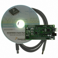
DEMO BOARD FOR MC56F8006
Manufacturer
Freescale Semiconductor
Type
DSPr
Datasheets
1.MC56F8006DEMO.pdf
(13 pages)
2.MC56F8006DEMO.pdf
(8 pages)
3.MC56F8006DEMO.pdf
(2 pages)
4.MC56F8006DEMO.pdf
(100 pages)
Specifications of MC56F8006DEMO
Contents
Board
Processor To Be Evaluated
MC56F8006
Interface Type
RS-232, USB
Operating Supply Voltage
3.3 V
Silicon Manufacturer
Freescale
Core Architecture
56800/E
Core Sub-architecture
56800/E
Silicon Core Number
MC56F
Silicon Family Name
MC56F80xx
Rohs Compliant
Yes
For Use With/related Products
MC56F8006
Lead Free Status / RoHS Status
Lead free / RoHS Compliant


Chapter 2
Technical Summary
2.1 Options
2.1.1 JP1: IRQ_SW1 Input Select
JP1 is a cutaway type option on the bottom side of the DEMO board. Default connection is to
MC56F8006 I/O port B2. Optional connection to port B4 is provided for user application.
2.1.2 JP2: IRQ_SW2 Input Select
JP2 is a cutaway type option on the bottom side of the DEMO board. Default connection is to
MC56F8006 I/O port B3. Optional connection to port B5 is provided for user application.
2.1.3 JP3: +3.3 V Enable
JP3 option installed (default) provides +3.3V regulated voltage from the onboard VR1 voltage
regulator to power the DEMO board. Open this option to power the board from an external +3.3V
source or from the J1 connector.
2.1.4 JP4: +Vopt Enable
JP4 option installed provides a connection from J1 pin 1 to the board +3.3V power connection.
This option is open/idle by default. This option may be applied to provide board +3.3 V regulated
voltage to the J1 connector (JP3 installed also) or to source +3.3V from J1 (JP3 open) to power
the board from a connected host platform.
2.1.5 TX_EN and RX_EN Option Jumpers
TX_EN and RX_EN options provide selection of the serial port connection for the MC56F8006 SCI
serial port. MC56F8006 ports B6 (RXD) and B7 (TXD) provide the SCI I/O pins for these options.
Default option setting is for the USB port to support the SCI serial port. The RS-232 serial port is
not populated by default but may be applied by the user if populated.
TX_EN and RX_EN = position 1–2 default, USB BDM serial port support.
Position 2–3 = RS-232 port.
See the support DVD for virtual terminal software to support the USB serial port.
2.2 User Components
2.2.1 LED1: 6 Indicators
Six indicator LEDs are provided for user application indications. The LEDs are applied to the
MC56F8006 I/O port A0/PWM0 to A5/PWM5 signals. Buffers are applied so that the LEDs will not
load the I/O port pins during operation. LEDs are on during the applied signals logic high level.
The following table provides the signal and LED reference.
LED
LED1
LED2
LED3
LED4
LED5
LED6
6
MC56F8006 I/O Port
PAO/PWM0
PA1/PWM1
PA2/PWM2
PA3/PWM3
PA4/PWM4
PA5/PWM5
LED Color
RED
RED
GREEN
GREEN
YELLOW
YELLOW
www.freescale.com
Related parts for MC56F8006DEMO
Image
Part Number
Description
Manufacturer
Datasheet
Request
R

Part Number:
Description:
Manufacturer:
Freescale Semiconductor, Inc
Datasheet:
Part Number:
Description:
Manufacturer:
Freescale Semiconductor, Inc
Datasheet:
Part Number:
Description:
Manufacturer:
Freescale Semiconductor, Inc
Datasheet:
Part Number:
Description:
Manufacturer:
Freescale Semiconductor, Inc
Datasheet:
Part Number:
Description:
Manufacturer:
Freescale Semiconductor, Inc
Datasheet:
Part Number:
Description:
Manufacturer:
Freescale Semiconductor, Inc
Datasheet:
Part Number:
Description:
Manufacturer:
Freescale Semiconductor, Inc
Datasheet:
Part Number:
Description:
Manufacturer:
Freescale Semiconductor, Inc
Datasheet:
Part Number:
Description:
Manufacturer:
Freescale Semiconductor, Inc
Datasheet:
Part Number:
Description:
Manufacturer:
Freescale Semiconductor, Inc
Datasheet:
Part Number:
Description:
Manufacturer:
Freescale Semiconductor, Inc
Datasheet:
Part Number:
Description:
Manufacturer:
Freescale Semiconductor, Inc
Datasheet:
Part Number:
Description:
Manufacturer:
Freescale Semiconductor, Inc
Datasheet:
Part Number:
Description:
Manufacturer:
Freescale Semiconductor, Inc
Datasheet:
Part Number:
Description:
Manufacturer:
Freescale Semiconductor, Inc
Datasheet: