28150 Parallax Inc, 28150 Datasheet - Page 3
28150
Manufacturer Part Number
28150
Description
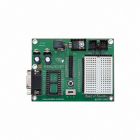
BOARD OF EDUCATION
Manufacturer
Parallax Inc
Series
BASIC Stamp® 2r
Type
MCUr
Specifications of 28150
Contents
Development Board
Product
Microcontroller Accessories
Board Size
127 mm x 57.2 mm x 38.1 mm
For Use With/related Products
BASIC Stamp® 2 and Board of Education
For Use With
900-00014 - SERVO CONTROLLER PICO GWS130-28029 - KIT PARTS SMART SENSORS28029PAR - KIT PARTS SMART SENSORS W/TEXT28030 - ADAPTER USB TO SERIAL RS232805-00006 - CABLE USB A TO MINI B27937 - MEMORY STICK DATALOGGER658-1021-5 - PROGRAMMER TEACLIPPER/STAMP30010 - BASIC STAMP LOGIC ANALYZER28022 - KIT DS2760 THERMOCOUPLE27964 - UNIPOLAR STEPPER MOTOR 12VDC27220 - BOOK STAMPWORKS27938 - MOTOR CONTROLLER LITTLE STEP-U27330 - PROGRAMMER STACHE BASIC STAMP27218 - MANUAL BASIC STAMP VER 2.028150 - BOARD OF EDUCATION
Lead Free Status / RoHS Status
Lead free / RoHS Compliant


Example Circuit
On the left is a simple circuit used to monitor light levels. The illustration on the right shows how this
circuit can be constructed on the BOE breadboard.
Power Switch
The BOE has a three-position power switch located at the bottom-center of the board. The leftmost
position (0) is OFF – all power is disconnected. Always place the switch in this position when adding or
changing components on the breadboard. The middle position (1) provides Vin to the regulator, the
BASIC Stamp IC socket, and to the connectors marked Vin. In this position, Vdd will also be available on
the breadboard and AppMod (see below) connectors. The rightmost position (2) provides power to the
servo connectors X4 and X5 (see servo power selection below).
The three-position position power switch is particularly convenient when using the BOE on small robots,
like the Parallax Boe-Bot
When ready for a full test, download your code, move the power switch to position 2, then reset and go!
Servo Power Selection
You can select the power provided to servo sockets X4 and X5 by a jumper that is located between these
two sockets; the default position is Vdd (+5 regulated). When using a six-volt battery pack (as on a
Boe-Bot robot, for example), you may wish to move this jumper to the Vin position to provide extra power
to the servos. When using Vin in the servo ports, always check to make sure the voltage supplied does
not exceed the specifications of the particular brand of servos you are using.
Reset Button
The reset button, located just above the power switch, can be used to restart your BASIC Stamp IC
without having to cycle the power. This saves wear-and-tear on the power switch for simple program
restarts.
BASIC Stamp IC I/O Access, Vdd, Vin, and Vss
The BASIC Stamp IC’s 16 I/O pins are brought to the X2 female socket left of the breadboard. I/O pins
are accessed by plugging wires into the header, then into the breadboard sockets. The X3 socket
provides four connection points for a +5V (Vdd) connection, unregulated input voltage (Vin), and ground
(Vss).
© Parallax, Inc. • BOE Rev C (#28150) • v1.2 01/2006
P0
220
®
Ω
. Use position 1 to edit and test code while power is removed from the servos.
Vdd
Vss
0.1 µF
P15
P14
P13
P12
P11
P10
P9
P8
P7
P6
P5
P4
P3
P2
P1
P0
X2
X3
Vdd
Vin
Vss
Page 3 of 5
Related parts for 28150
Image
Part Number
Description
Manufacturer
Datasheet
Request
R


Part Number:
Description:
Microcontroller Modules & Accessories DISCONTINUED BY PARALLAX
Manufacturer:
Parallax Inc

Part Number:
Description:
BOOK UNDERSTANDING SIGNALS
Manufacturer:
Parallax Inc
Datasheet:


Part Number:
Description:
COMPETITION RING FOR SUMOBOT
Manufacturer:
Parallax Inc
Datasheet:


Part Number:
Description:
TEXT INFRARED REMOTE FOR BOE-BOT
Manufacturer:
Parallax Inc
Datasheet:
Part Number:
Description:
BOARD EXPERIMENT+LCD NX-1000
Manufacturer:
Parallax Inc
Datasheet:

Part Number:
Description:
CONTROLLER 16SERVO MOTOR CONTROL
Manufacturer:
Parallax Inc
Datasheet:

Part Number:
Description:
BASIC STAMP LOGIC ANALYZER
Manufacturer:
Parallax Inc
Datasheet:

Part Number:
Description:
IC MCU 2K FLASH 50MHZ SO-18
Manufacturer:
Parallax Inc
Datasheet: