ATEVK1104S Atmel, ATEVK1104S Datasheet - Page 6
ATEVK1104S
Manufacturer Part Number
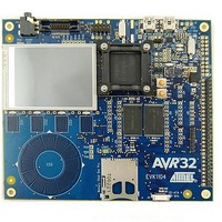
ATEVK1104S
Description
KIT EVAL FOR AT32UC
Manufacturer
Atmel
Series
AVR®32 UC3r
Type
MCUr
Specifications of ATEVK1104S
Contents
Board, Cables
Tool Type
Development Kit
Cpu Core
AVR 32
Data Bus Width
32 bit
Processor Series
AT32
Processor To Be Evaluated
AT32UC3A3256S
Interface Type
USB, JTAG, SD Card, Nexus, MMC
Core Architecture
AVR
Operating Supply Voltage
5.5 V
For Use With/related Products
*
Lead Free Status / RoHS Status
Lead free / RoHS Compliant


3.4 Signal generation
3.5 Basic Filtering
6
AVR32908
Zooming:
•
•
Reset application:
•
To provide a complex input signal to the DSP filters, the application generates two
sine signals using the dsp16_gen_sin() function found in the Signal Generation
category of the DSP library.
This function fills a vector (buffer) with a sinusoidal signal of a specified frequency
and sampling rate. This function is used to change the input frequency of our source
signals.
Generating different input signals:
•
•
•
•
A basic filter function is a function that suppresses (reduces) selected frequencies in
a signal. Filters are applied to extract useful information from a signal, either by
removing unwanted signals (noise) or extracting useful frequencies that lie within a
given frequency range. In audio applications, filters are applied to split the audio
signal into bass and treble channels. In RF communication, filters are used to remove
the carrier frequency.
A wide range of filters exist, but they are usually categorized into 4 categories:
Select the combined input signal at the middle of the screen.
Press and hold the FUNC3 button to zoom on the graph.
Press and hold the BACK button for 3 seconds (or push the RESET button) to
reset the source signals and filters and return the application to its initial state.
Push and hold the BACK button for 3 seconds to reset the signals and filters.
Turn the wheel to select Source 1.
Push FUNC 2 to select frequency setting.
Turn the wheel and observe how the frequency of the source signal can be
modified.
•
•
•
•
Low pass filters allow frequencies below the cutoff frequency to pass
through, and suppresses frequencies above it.
High pass filters allow frequencies above the cutoff frequency to pass
through.
Band pass filters combine a low pass filter and a high pass filter to allow
only frequencies in a limited frequency band (range) to pass through.
Advanced filters make use of advanced signal processing theory to extract
useful information spread across multiple frequencies.
32138A-AVR32-02/10
Related parts for ATEVK1104S
Image
Part Number
Description
Manufacturer
Datasheet
Request
R

Part Number:
Description:
DEV KIT FOR AVR/AVR32
Manufacturer:
Atmel
Datasheet:

Part Number:
Description:
INTERVAL AND WIPE/WASH WIPER CONTROL IC WITH DELAY
Manufacturer:
ATMEL Corporation
Datasheet:
Part Number:
Description:
Low-Voltage Voice-Switched IC for Hands-Free Operation
Manufacturer:
ATMEL Corporation
Datasheet:
Part Number:
Description:
MONOLITHIC INTEGRATED FEATUREPHONE CIRCUIT
Manufacturer:
ATMEL Corporation
Datasheet:
Part Number:
Description:
AM-FM Receiver IC U4255BM-M
Manufacturer:
ATMEL Corporation
Datasheet:
Part Number:
Description:
Monolithic Integrated Feature Phone Circuit
Manufacturer:
ATMEL Corporation
Datasheet:
Part Number:
Description:
Multistandard Video-IF and Quasi Parallel Sound Processing
Manufacturer:
ATMEL Corporation
Datasheet:
Part Number:
Description:
High-performance EE PLD
Manufacturer:
ATMEL Corporation
Datasheet:
Part Number:
Description:
8-bit Flash Microcontroller
Manufacturer:
ATMEL Corporation
Datasheet:
Part Number:
Description:
2-Wire Serial EEPROM
Manufacturer:
ATMEL Corporation
Datasheet: