M53015EVB Freescale Semiconductor, M53015EVB Datasheet - Page 6
M53015EVB
Manufacturer Part Number
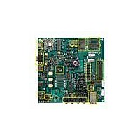
M53015EVB
Description
KIT DEVELOPMENT FOR MCF53015
Manufacturer
Freescale Semiconductor
Type
MPUr
Specifications of M53015EVB
Contents
Board, Cables, Cards, Power Supply Kit
Processor To Be Evaluated
MCF5301
Data Bus Width
32 bit
Interface Type
Ethernet, USB, UART, SPI, I2C
Maximum Operating Temperature
+ 85 C
Minimum Operating Temperature
- 40 C
Operating Supply Voltage
3.6 V
Silicon Manufacturer
Freescale
Core Architecture
Coldfire
Core Sub-architecture
Coldfire V3
Silicon Core Number
MCF53
Silicon Family Name
MCF5301x
Rohs Compliant
Yes
For Use With/related Products
MCF53015
Lead Free Status / RoHS Status
Lead free / RoHS Compliant


5.3
Four on-board clock sources are provided on the M53015EVB -- a 20MHz oscillator, a 32.768KHz
oscillator, programmable clock generator, and a 20MHz crystal. Alternatively, an input clock signal can
be provided via an SMA connector for test purposes. The different clock signals and configurations are
described below. Please refer to the MCF53017 Reference Manual for further information on the clocking
requirements for the MCF53015.
5.4
The program flash memory on the M53015EVB resides on the first block of FlexBus memory. The
128Mbit Spansion flash can be used for RTOS development. Your software must configure the memory
access parameters consistent with the hardware configuration.
Jumper J33 controls the boot mode of the flash. The default position is 2-3 which selects bottom boot
mode. Setting the jumper to position 1-2, selects top boot mode. This flash device is connected to CS0 and
is the device from which the MCF53015 executes following reset.
5.5
512 KB of MRAM are included on the M53015EVB. The MRAM is connected to CS1. The MRAM is a
3.3V part, so level translators are used to interface it to the 1.8V FlexBus.
5.6
The M53015EVB has a 256 KB serial EEPROM connected to the I2C bus that can be used for boot loader
program storage.
6
20MHz Input Oscillator
32.768KHz Oscillator
20MHz Input Crystal
External Clock Input
Clock Generator
System Clocks
Program Flash Memory
MRAM
Serial EEPROM
Clock
If the clock selection is changed, the SW5-3 switch setting should be
changed to reflect the appropriate clock input.
Jumpers J29 and J31 are used to select between clock options. Setting J29
to 2-3 and J31 to 1-2 selects the 20MHz Oscillator option. In this mode, H21
should be populated to pull the XTAL up.
Setting J31 to 2-3 selects the 20MHz Crystal option. In this mode, H21
should not be populated and the setting of J21 is a don’t care.
Setting J29 to1-2 and J31 to 1-2 selects the External Clock Input option.
The external clock can be input on the SMA connector J46.
Jumpers J42 and J43 are used to select between Real Time Clock options.
Setting J42 to 2-3 and J43 to 1-2 selects the 32.768KHz Oscillator option
as an input. The default setting for J43 is 2-3 where the processor provides
the 32.768KHz output clock.
In circuit programmable via the I2C interface.
Table 2. M53015EVB Clock Definitions
M53015 Evaluation Board, Rev. 0.5
NOTE
Description
Freescale Semiconductor
Programmable
Frequency
32.768KHz
Variable
20MHz
20MHz
Related parts for M53015EVB
Image
Part Number
Description
Manufacturer
Datasheet
Request
R

Part Number:
Description:
Manufacturer:
Freescale Semiconductor, Inc
Datasheet:
Part Number:
Description:
Manufacturer:
Freescale Semiconductor, Inc
Datasheet:
Part Number:
Description:
Manufacturer:
Freescale Semiconductor, Inc
Datasheet:
Part Number:
Description:
Manufacturer:
Freescale Semiconductor, Inc
Datasheet:
Part Number:
Description:
Manufacturer:
Freescale Semiconductor, Inc
Datasheet:
Part Number:
Description:
Manufacturer:
Freescale Semiconductor, Inc
Datasheet:
Part Number:
Description:
Manufacturer:
Freescale Semiconductor, Inc
Datasheet:
Part Number:
Description:
Manufacturer:
Freescale Semiconductor, Inc
Datasheet:
Part Number:
Description:
Manufacturer:
Freescale Semiconductor, Inc
Datasheet:
Part Number:
Description:
Manufacturer:
Freescale Semiconductor, Inc
Datasheet:
Part Number:
Description:
Manufacturer:
Freescale Semiconductor, Inc
Datasheet:
Part Number:
Description:
Manufacturer:
Freescale Semiconductor, Inc
Datasheet:
Part Number:
Description:
Manufacturer:
Freescale Semiconductor, Inc
Datasheet:
Part Number:
Description:
Manufacturer:
Freescale Semiconductor, Inc
Datasheet:
Part Number:
Description:
Manufacturer:
Freescale Semiconductor, Inc
Datasheet: