R0K561622S000BE Renesas Electronics America, R0K561622S000BE Datasheet - Page 11
R0K561622S000BE
Manufacturer Part Number
R0K561622S000BE
Description
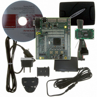
KIT STARTER FOR H8SX/1622
Manufacturer
Renesas Electronics America
Series
Renesas Starter Kits (RSK)r
Type
MCUr
Specifications of R0K561622S000BE
Contents
Board, Cables, CD, Debugger, Power Supply
Silicon Manufacturer
Renesas
Features
Coding And Debugging, E10A Emulator, RS232 Serial Connection
Kit Contents
Board
Silicon Family Name
H8SX/1622F
Silicon Core Number
R5F61622N50LGV
Lead Free Status / RoHS Status
Lead free / RoHS Compliant
For Use With/related Products
H8SX/1622
Lead Free Status / RoHS Status
Lead free / RoHS Compliant, Lead free / RoHS Compliant


6.1. Switches
There are four switches located on the CPU board. The function of each switch and its connection are shown in Table 6-1.
*Refer to schematic for detailed connectivity information.
6.2. LEDs
There are six LEDs on the RSK board. The green ‘POWER’ LED lights when the board is powered. The orange BOOT LED indicates the
device is in BOOT mode when lit. The four user LEDs are connected to an IO port and will light when their corresponding port pin is set low.
Table 6-2, below, shows the LED pin references and their corresponding microcontroller port pin connections.
6.3. Potentiometer
A single turn potentiometer is connected to AN0 (P5.0) of the microcontroller. This may be used to vary the input analogue voltage value to
this pin between AVCC and Ground.
6.4. Serial port
Serial port SCI2 is connected to the standard RS232 header. Serial ports SCI4 can optionally be connected to the RS232 header by fitting
option resistors. The connections to be fitted are listed in the Table 6-3.
RES
SW1/BOOT*
SW2*
SW3*
LED0
LED1
LED2
LED3
shown on silkscreen)
LED Reference (As
Switch
When pressed, the RSK microcontroller is reset.
Connects to an IRQ input for user controls.
The switch is also used in conjunction with the RES switch to place the device in
BOOT mode when not using the E10A debugger.
Connects to an IRQ line for user controls.
Connects to the ADC trigger input. Option link allows connection to IRQ line.
The option is a pair of 0R links. For more details on option links, please refer to
Sec 6.6.
Chapter 6. User Circuitry
Green
Orange
Red
Red
Table 6-1: Switch Functions
Colour
Table 6-2: LED Port
Function
9
Port A.0
Port A.2
Port 1.7
Port 1.6
Microcontroller Port Pin
function
Microcontroller
17
19
60
62
RESn, Pin91
IRQ4n, Pin 124
(Port 5, pin 4)
IRQ5n, Pin 126
(Port 5, pin 5)
IRQ3n_ADTRGn,
Pin 66
(Port 1, pin 3)
Microcontroller
Pin Number
Related parts for R0K561622S000BE
Image
Part Number
Description
Manufacturer
Datasheet
Request
R

Part Number:
Description:
KIT STARTER FOR M16C/29
Manufacturer:
Renesas Electronics America
Datasheet:

Part Number:
Description:
KIT STARTER FOR R8C/2D
Manufacturer:
Renesas Electronics America
Datasheet:

Part Number:
Description:
R0K33062P STARTER KIT
Manufacturer:
Renesas Electronics America
Datasheet:

Part Number:
Description:
KIT STARTER FOR R8C/23 E8A
Manufacturer:
Renesas Electronics America
Datasheet:

Part Number:
Description:
KIT STARTER FOR R8C/25
Manufacturer:
Renesas Electronics America
Datasheet:

Part Number:
Description:
KIT STARTER H8S2456 SHARPE DSPLY
Manufacturer:
Renesas Electronics America
Datasheet:

Part Number:
Description:
KIT STARTER FOR R8C38C
Manufacturer:
Renesas Electronics America
Datasheet:

Part Number:
Description:
KIT STARTER FOR R8C35C
Manufacturer:
Renesas Electronics America
Datasheet:

Part Number:
Description:
KIT STARTER FOR R8CL3AC+LCD APPS
Manufacturer:
Renesas Electronics America
Datasheet:
Part Number:
Description:
KIT STARTER FOR RX610
Manufacturer:
Renesas Electronics America
Datasheet:

Part Number:
Description:
KIT STARTER FOR R32C/118
Manufacturer:
Renesas Electronics America
Datasheet:

Part Number:
Description:
KIT DEV RSK-R8C/26-29
Manufacturer:
Renesas Electronics America
Datasheet:

Part Number:
Description:
KIT STARTER FOR SH7124
Manufacturer:
Renesas Electronics America
Datasheet:

Part Number:
Description:
KIT DEV FOR SH7203
Manufacturer:
Renesas Electronics America
Datasheet:
Part Number:
Description:
KIT STARTER FOR R8C/18191A1B
Manufacturer:
Renesas Electronics America
Datasheet: