R0K570865S000BE Renesas Electronics America, R0K570865S000BE Datasheet - Page 20
R0K570865S000BE
Manufacturer Part Number
R0K570865S000BE
Description
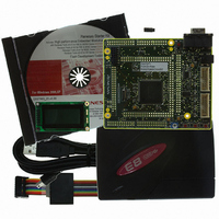
KIT STARTER FOR SH7086
Manufacturer
Renesas Electronics America
Series
Renesas Starter Kits (RSK)r
Type
MCUr
Specifications of R0K570865S000BE
Contents
CPU Board, LCD Display Module, E8 Emulator, Cable, QuickStart Guide and CD-ROM
For Use With/related Products
SH7086
Lead Free Status / RoHS Status
Contains lead / RoHS non-compliant


All of the Flash ROM on the device can be programmed when the device is in Boot mode. In boot mode, the boot-loader program
pre-programmed into the microcontroller executes and attempts a connection with the host (for example a PC). On establishing a
connection with the microcontroller, the host may then transmit program data to the microcontroller via the appropriate programming port.
The programming port for this Renesas Microcontroller and its associated pins are detailed in Table 8-1: Serial Port Boot Channel
8.1. Programming with the E8
The Flash Development Toolkit (FDT) is supplied to allow programs to be loaded directly on to the board using the E8. The E8 resets the
CPU invoking the User Program mode described above. This starts the FDT User Program mode programming kernel. For further
information see the User program sample code and the FDT kernel code.
8.2. E10A Header
This device supports E10A debugging interface. The E10A provides additional debugging features including hardware breakpoints and
hardware trace capability. (Check with the website at
8.3. Serial Port Programming
This sequence is not required when debugging using the E8 supplied with the kit.
The microcontroller must enter boot mode for programming, and the programming port must be connected to a host for program download.
To execute the boot transition, and allow programs to download to the microcontroller, the user must perform the following procedure:
Ensure the relevant option links are made from Table 6-3: Serial Options Links
Connect a 1:1 serial cable between the host PC and the CPU board.
Depress the BOOT switch and keep this held down.
Depress the RESET switch once, and release.
Release the BOOT switch.
The Flash Development Toolkit (FDT) is supplied to allow programs to be loaded directly on to the board using this method.
SCI1
CPU board Signal Name
Programming Port Table – Programming port pins and their CPU board signal names
Chapter 8. Programming Methods
TXD1, Pin 169
PTTX
Table 8-1: Serial Port Boot Channel
www.renesas.com
15
or your distributor for a full feature list).
RXD1, Pin 167
PTRX
Related parts for R0K570865S000BE
Image
Part Number
Description
Manufacturer
Datasheet
Request
R

Part Number:
Description:
KIT STARTER FOR M16C/29
Manufacturer:
Renesas Electronics America
Datasheet:

Part Number:
Description:
KIT STARTER FOR R8C/2D
Manufacturer:
Renesas Electronics America
Datasheet:

Part Number:
Description:
R0K33062P STARTER KIT
Manufacturer:
Renesas Electronics America
Datasheet:

Part Number:
Description:
KIT STARTER FOR R8C/23 E8A
Manufacturer:
Renesas Electronics America
Datasheet:

Part Number:
Description:
KIT STARTER FOR R8C/25
Manufacturer:
Renesas Electronics America
Datasheet:

Part Number:
Description:
KIT STARTER H8S2456 SHARPE DSPLY
Manufacturer:
Renesas Electronics America
Datasheet:

Part Number:
Description:
KIT STARTER FOR R8C38C
Manufacturer:
Renesas Electronics America
Datasheet:

Part Number:
Description:
KIT STARTER FOR R8C35C
Manufacturer:
Renesas Electronics America
Datasheet:

Part Number:
Description:
KIT STARTER FOR R8CL3AC+LCD APPS
Manufacturer:
Renesas Electronics America
Datasheet:
Part Number:
Description:
KIT STARTER FOR RX610
Manufacturer:
Renesas Electronics America
Datasheet:

Part Number:
Description:
KIT STARTER FOR R32C/118
Manufacturer:
Renesas Electronics America
Datasheet:

Part Number:
Description:
KIT DEV RSK-R8C/26-29
Manufacturer:
Renesas Electronics America
Datasheet:

Part Number:
Description:
KIT STARTER FOR SH7124
Manufacturer:
Renesas Electronics America
Datasheet:

Part Number:
Description:
KIT STARTER FOR H8SX/1622
Manufacturer:
Renesas Electronics America
Datasheet:

Part Number:
Description:
KIT DEV FOR SH7203
Manufacturer:
Renesas Electronics America
Datasheet: