C8051F310DK Silicon Laboratories Inc, C8051F310DK Datasheet - Page 149
C8051F310DK
Manufacturer Part Number
C8051F310DK
Description
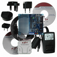
DEV KIT FOR C8051F310/F311
Manufacturer
Silicon Laboratories Inc
Type
MCUr
Specifications of C8051F310DK
Contents
Evaluation Board, Power Supply, USB Cables, Adapter and Documentation
Processor To Be Evaluated
C8051F31x
Interface Type
USB
Silicon Manufacturer
Silicon Labs
Core Architecture
8051
Silicon Core Number
C8051F310
Silicon Family Name
C8051F31x
Lead Free Status / RoHS Status
Contains lead / RoHS non-compliant
For Use With/related Products
Silicon Laboratories C8051, F310, 311 MCUs
Lead Free Status / Rohs Status
Lead free / RoHS Compliant
Other names
336-1253
Available stocks
Company
Part Number
Manufacturer
Quantity
Price
Company:

Part Number:
C8051F310DK
Manufacturer:
SiliconL
Quantity:
10


14.4. Using the SMBus
The SMBus can operate in both Master and Slave modes. The interface provides timing and shifting con-
trol for serial transfers; higher level protocol is determined by user software. The SMBus interface provides
the following application-independent features:
•
•
•
•
•
•
•
SMBus interrupts are generated for each data byte or slave address that is transferred. When transmitting,
this interrupt is generated after the ACK cycle so that software may read the received ACK value; when
receiving data, this interrupt is generated before the ACK cycle so that software may define the outgoing
ACK value. See
sequences.
Interrupts are also generated to indicate the beginning of a transfer when a master (START generated), or
the end of a transfer when a slave (STOP detected). Software should read the SMB0CN (SMBus Control
register) to find the cause of the SMBus interrupt. The SMB0CN register is described in
“14.4.2. SMB0CN Control Register” on page
ence.
SMBus configuration options include:
•
•
•
•
These options are selected in the SMB0CF register, as described in
tion Register” on page
Byte-wise serial data transfers
Clock signal generation on SCL (Master Mode only) and SDA data synchronization
Timeout/bus error recognition, as defined by the SMB0CF configuration register
START/STOP timing, detection, and generation
Bus arbitration
Interrupt generation
Status information
Timeout detection (SCL Low Timeout and/or Bus Free Timeout)
SDA setup and hold time extensions
Slave event enable/disable
Clock source selection
Section “14.5. SMBus Transfer Modes” on page 157
150.
153; Table 14.4 provides a quick SMB0CN decoding refer-
Rev. 1.7
C8051F310/1/2/3/4/5/6/7
Section “14.4.1. SMBus Configura-
for more details on transmission
Section
149
Related parts for C8051F310DK
Image
Part Number
Description
Manufacturer
Datasheet
Request
R

Part Number:
Description:
SMD/C°/SINGLE-ENDED OUTPUT SILICON OSCILLATOR
Manufacturer:
Silicon Laboratories Inc
Part Number:
Description:
Manufacturer:
Silicon Laboratories Inc
Datasheet:
Part Number:
Description:
N/A N/A/SI4010 AES KEYFOB DEMO WITH LCD RX
Manufacturer:
Silicon Laboratories Inc
Datasheet:
Part Number:
Description:
N/A N/A/SI4010 SIMPLIFIED KEY FOB DEMO WITH LED RX
Manufacturer:
Silicon Laboratories Inc
Datasheet:
Part Number:
Description:
N/A/-40 TO 85 OC/EZLINK MODULE; F930/4432 HIGH BAND (REV E/B1)
Manufacturer:
Silicon Laboratories Inc
Part Number:
Description:
EZLink Module; F930/4432 Low Band (rev e/B1)
Manufacturer:
Silicon Laboratories Inc
Part Number:
Description:
I°/4460 10 DBM RADIO TEST CARD 434 MHZ
Manufacturer:
Silicon Laboratories Inc
Part Number:
Description:
I°/4461 14 DBM RADIO TEST CARD 868 MHZ
Manufacturer:
Silicon Laboratories Inc
Part Number:
Description:
I°/4463 20 DBM RFSWITCH RADIO TEST CARD 460 MHZ
Manufacturer:
Silicon Laboratories Inc
Part Number:
Description:
I°/4463 20 DBM RADIO TEST CARD 868 MHZ
Manufacturer:
Silicon Laboratories Inc
Part Number:
Description:
I°/4463 27 DBM RADIO TEST CARD 868 MHZ
Manufacturer:
Silicon Laboratories Inc
Part Number:
Description:
I°/4463 SKYWORKS 30 DBM RADIO TEST CARD 915 MHZ
Manufacturer:
Silicon Laboratories Inc
Part Number:
Description:
N/A N/A/-40 TO 85 OC/4463 RFMD 30 DBM RADIO TEST CARD 915 MHZ
Manufacturer:
Silicon Laboratories Inc
Part Number:
Description:
I°/4463 20 DBM RADIO TEST CARD 169 MHZ
Manufacturer:
Silicon Laboratories Inc