DEMO908GZ60E Freescale Semiconductor, DEMO908GZ60E Datasheet - Page 2
DEMO908GZ60E
Manufacturer Part Number
DEMO908GZ60E
Description
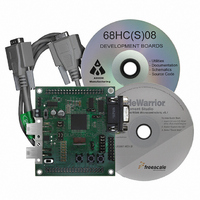
BOARD DEMO FOR 908GZ60 MCU
Manufacturer
Freescale Semiconductor
Series
HC08GRr
Type
MCUr
Specifications of DEMO908GZ60E
Design Resources
DEMO908GZ60E Schematic
Contents
Board, Cable, CD
Processor To Be Evaluated
908GZ
Data Bus Width
16 bit
Interface Type
RS-232
For Use With/related Products
68HC908GZ60
Lead Free Status / RoHS Status
Lead free / RoHS Compliant


Introduction and Default Settings
Connect the DEMO908GZ60 to your computer and apply power
Run the DEMO908GZ60_LED program
The DEMO908GZ60 is shipped with the DEMO908GZ60_LED stored in on-chip Flash memory. You may
view the source code for this program by accessing the “DEMO908GZ60_LED.zip” file on the Axiom CD
(located in the “examples” folder).
Install CodeWarrior Development Studio Version 3.1 for HC(S)08
If you do not have version 3.1 of CodeWarrior for HC(S)08 Special Edition installed on your computer,
please refer to the provided “CodeWarrior Development Studio for Motorola” CD for HC(S)08 Special
Edition Version 3.1 and the included CodeWarrior Quick Start. Important: You must register and obtain
a license key to use CodeWarrior. You must also obtain another special edition license key, which will
allow you to experience all the features of the CodeWarrior debugger (see install, register, and license
key instructions in the CodeWarrior Quick Start).
Use the MON08 Monitor to install DEMO908GZ60_ATD program
The MON08 Monitor allows a user to program the MCU Flash and debug application via serial connection.
2
1. Connect the 9-pin serial cable provided to the COM1 port of the DEMO board. Connect the other
2. There are two ways to apply power to the demo board: via the power terminal block or the J1
1. Press SW1 and LED1 will turn on. Release SW1 and LED1 should turn off.
2. Press SW2 and LED2 will turn on. Release SW2 and LED2 should turn off.
1. On the Axiom CD (examples folder), copy and open the “DEMO908GZ60_ATD.zip” file to your PC,
2. If you have not already done so, connect serial cable and apply power to the board.
3. In the working folder on the desktop, double click on the “DEMO908GZ60.mcp” project file. The
4. Open “DEMO908GZ60_ATD.c” in the source folder by double clicking on
5. Please change the jumpers on the board to ensure proper communication between the PC and
Please Note: +9 VDC supply must be used for proper MON08 monitor operation.
end to a COM port on your host PC.
MCU_PORT. Refer to the DEMO908GZ60 User’s Guide about using the MCU_PORT. Otherwise,
connect the +9 VDC supply into the screw-type terminal block. Please review the diagram above
for wire placement. Apply power to the power and turn on the power switch. The +5V LED should
turn on. If the LED is not on, please check the PWR_SEL jumpers, PWR switch, and the placement
of the +9 VDC power supply wires.
and extract the files into a working folder on your desktop. Note: Be sure to extract, and not just
copy, the files.
CodeWarrior IDE will launch.
“DEMO908GZ60_ATD.c”.
DEMO908GZ60 board.
DEMO908GZ60 Quick Start Guide, Rev. 0.0
Freescale Semiconductor
Related parts for DEMO908GZ60E
Image
Part Number
Description
Manufacturer
Datasheet
Request
R

Part Number:
Description:
Manufacturer:
Freescale Semiconductor, Inc
Datasheet:
Part Number:
Description:
Manufacturer:
Freescale Semiconductor, Inc
Datasheet:
Part Number:
Description:
Manufacturer:
Freescale Semiconductor, Inc
Datasheet:
Part Number:
Description:
Manufacturer:
Freescale Semiconductor, Inc
Datasheet:
Part Number:
Description:
Manufacturer:
Freescale Semiconductor, Inc
Datasheet:
Part Number:
Description:
Manufacturer:
Freescale Semiconductor, Inc
Datasheet:
Part Number:
Description:
Manufacturer:
Freescale Semiconductor, Inc
Datasheet:
Part Number:
Description:
Manufacturer:
Freescale Semiconductor, Inc
Datasheet:
Part Number:
Description:
Manufacturer:
Freescale Semiconductor, Inc
Datasheet:
Part Number:
Description:
Manufacturer:
Freescale Semiconductor, Inc
Datasheet:
Part Number:
Description:
Manufacturer:
Freescale Semiconductor, Inc
Datasheet:
Part Number:
Description:
Manufacturer:
Freescale Semiconductor, Inc
Datasheet:
Part Number:
Description:
Manufacturer:
Freescale Semiconductor, Inc
Datasheet:
Part Number:
Description:
Manufacturer:
Freescale Semiconductor, Inc
Datasheet:
Part Number:
Description:
Manufacturer:
Freescale Semiconductor, Inc
Datasheet: