STM8L101-EVAL STMicroelectronics, STM8L101-EVAL Datasheet
STM8L101-EVAL
Specifications of STM8L101-EVAL
Available stocks


Related parts for STM8L101-EVAL


STM8L101-EVAL Summary of contents
Page 1
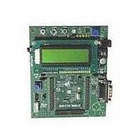
... An STM8L1 daughterboard called MB710 which has an STM8L101 MCU. The motherboard and daughterboard are a complete development platform for STMicroelectronic's STM8L101 microcontroller with comparator, I2C, SPI, USART and SWIM debugging support. The full range of hardware features on the STM8L101-EVAL helps you to evaluate all peripherals (MicroSD card applications. Figure 1. ...
Page 2
Contents Contents 1 Overview . . . . . . . . . . . . . . . . . . . . . . . . . . . . . . . . . . . . ...
Page 3
... UM0629 Appendix A STM8L101-EVAL I/O assignment . . . . . . . . . . . . . . . . . . . . . . . . . . . 24 5 Revision history . . . . . . . . . . . . . . . . . . . . . . . . . . . . . . . . . . . . . . . . . . . 25 Doc ID 15312 Rev 2 Contents 3/26 ...
Page 4
... Demonstration software is preloaded in the board’s Flash memory for easy demonstration of device peripherals in stand-alone mode. For more information and to download the latest version available, refer to STM8L101-EVAL demonstration firmware available on web: www.st.com/mcu. 1.3 Order code To order the STM8L101K3 evaluation board, use the order code STM8L101-EVAL. 4/26 TM Doc ID 15312 Rev 2 UM0629 ...
Page 5
... UM0629 1.4 Hardware layout and configuration The STM8L101-EVAL evaluation board is designed around the STM8L101K3T6 in an LQFP32 package. Figure 2 illustrates the connections between the daughterboard and the peripherals on the motherboard (LCD, I2C EEPROM, USART, audio and MicroSD card). Figure 3 and Figure 4 Figure 2. ...
Page 6
Overview Figure 3. STM8L1/L2 motherboard layout CN3, CN4 daughterboard connectors RV4 MCU_VDD adjustment 6/ RESET Joystick KEY Doc ID 15312 Rev 2 UM0629 CN6 SWIM (ERNI cable alternative) CN5 SWIM RV1 Potentiometer CN8 USART U2 Dot-matrix LCD ...
Page 7
... UM0629 Figure 4. STM8L1 daughterboard layout CN1, CN2 motherboard connector and footprint for socket (ref ENPLAS OTQ-32-0.8-02) is present on the board STM8L101 MCU in LQFP32 package soldered directly onto the board Doc ID 15312 Rev 2 Overview 7/26 ...
Page 8
STM8L1/L2 motherboard 2 STM8L1/L2 motherboard This motherboard is designed to work with an STM8L1 daughterboard. 2.1 Power supply The motherboard is designed to be powered power supply and to be protected from a wrong power ...
Page 9
... Reset source The reset signal of the motherboard is low active. Reset sources include: Reset button B1. Debugging tools from connectors CN5, CN6. The reset pin PA1 of the STM8L101 is either connected to the reset button GND by the setting of jumper JP1: Table 2. Reset related jumpers Jumper PA1 is connected to GND when JP1 is set as shown to the right: This configuration is reserved for internal use only ...
Page 10
... Section 2.15 for details on RS-232 connector pinout. 2.6 MicroSD card The 1GByte (or more) MicroSD card connected to the SPI of the STM8L101 through a voltage level translator U1 (shared with LCD) is available on the board. MicroSD card chip select is managed by standard I/O port PB4. 2.7 Analog input The BNC connector footprint present on the board (CN7) cannot be used not connected to the MCU ...
Page 11
... Bi-color LED A bi-color LED is connected to PB0 through a voltage translator which guarantees that the bi-color LED works when the STM8L101 is powered by an adjustable voltage from 1 3.3 V. 2.11 Economic measurement and potentiometer RV1 The economic measurement solution is demonstrated based on the internal comparator inside the STM8L101 and potentiometer RV1 ...
Page 12
STM8L1/L2 motherboard Figure 5. Voltage measurement using internal comparator Table 6. Potentiometer RV1 related jumpers Jumper RV1 is connected to PD2 as one input of the internal comparator when JP2 is set as shown to the right: JP2 position is ...
Page 13
UM0629 Table 7. MicroSD connector CN1 Pin number 2.13 Daughterboard extension connectors CN3 and CN4 Two 36-pin male headers CN3 and CN4 can be used to connect the daughterboard to the motherboard. All GPI/Os are ...
Page 14
STM8L1/L2 motherboard Table 9. Daughterboard extension connector CN4 Pin number 2.14 SWIM connectors CN5 and CN6 CN6 is a low cost 2.54 ...
Page 15
UM0629 2.15 RS-232 connector CN8 Figure 8. RS-232 connector CN8 viewed from front Table 11. RS-232 connector CN8 Pin number 2.16 Audio jack CN9 A 3.5 mm mono audio jack CN9 is available on the ...
Page 16
... STM8L1 daughterboard 3 STM8L1 daughterboard 3.1 Power The STM8L101 MCU is powered by MCU_VDD from the motherboard through an extension connector on the board enabled by setting the jumper JP1 as described in Table 12. Power related jumper* Jumper Enables consumption measurement of VDD when the jumper is removed and replaced by an ammeter. ...
Page 17
... LED2 LED1 LED1 SPI_MISO BiD_LED BiD_LED SPI_MOSI USART_RX USART_RX SPI_SCK USART_TX USART_TX MicroSD_CS User_Button User_Button LCD_CS JOY_UP JOY_UP SDcard_detect JOY_RIGHT JOY_RIGHT JOY_LEFT JOY_LEFT JOY_DOWN JOY_DOWN JOY_SEL JOY_SEL Potentiometer Potentiometer BNC BNC STMicroelectronics Title: STM8L1/L2-MB Number: MB709 Rev: A.1(PCB.SCH) Date: 1/21/2009 Sheet ...
Page 18
... Exension connector Not Fitted STice connector STMicroelectronics Title: STM8L1/L2-MB MCU Number: MB709 Rev: A.1(PCB.SCH) Date: 10/12/2009 PA2 PG4 PG6 PA4 PA6 VDDA PG1 PG3 PD1 PD3 PB1 ...
Page 19
... GND THREE_STATE do not fit MAX3378EEUD R69 0 MCU_VDD CN1 10 8 SW1 SDcard_detect 9 7 SW2 PJS008-2000 (SMS064FF or SMS128FF) MicroSD card +3V3 R2 C3 +3V3 U2 do not fit 100nF 1 Vss 2 Vcc CLK 5 SID HXM122032-GB1 LCD +5V STMicroelectronics Title: STM8L1/L2-MB LCD&SD Number: MB709 Rev: A.1(PCB.SCH) Date: 1/21/2009 ...
Page 20
... R23 0 VSS SDA M24C64-RMN6 U7 R45 5 COMMON 100 MCU_VDD 2 Selection R24 0 R25 0 3 DWON R26 0 1 LEFT R27 0 4 RIGHT R28 MT008-A STMicroelectronics Title: STM8L1/L2-MB Peripherals Number: MB709 Rev: A.1(PCB.SCH) Date: 1/21/2009 Sheet 3 4 +5V R36 300 R16 300 I2C_SLK I2C_SDA EEPROM Joystick ...
Page 21
... C39 R63 2 680 180pF R65 82K C41 4.7uF Microphone Speaker CN9 1 KDMG15008- ST-613 Speaker+ 5 Uout1 8 +3V3 Vout2 6 VCC 7 GND C36 C27 100uF 100nF TP2 MIC_OUT R49 0 MIC_OUT C38 do not fit STMicroelectronics Title: STM8L1/L2-MB Audio Number: MB709 Rev: A.1(PCB.SCH) Date: 1/21/2009 Sheet ...
Page 22
... TP4 +3V3 U14 LD1086D2M33 +3V3 MCU_VDD Vin Vout 2 C45 C48 3 10uF 100nF JP11 TP5 U16 VCC_ADJ LD1086D2M VCC_ADJ 3 2 Vin Vout R67 C49 165 100nF C46 R68 10uF 75 2 RV4 3314J-201 STMicroelectronics Title: STM8L1/L2-MB Power Number: MB709 Rev: A.1(PCB.SCH) Date: 9/23/2009 ...
Page 23
... JP1 VSS 8 VDD PD0 9 PD0/TIM3_CH2/COMP1_CH3 C3 PD1 10 PD1/TIM3_TRIG/COMP1_CH4 100nF PD2 11 PD2/COMP2_CH3 PD3 12 PD3/COMP2_CH4 PB0 13 PB0/TIM2_CH1/COMP1_CH1 PB1 14 PB1/TIM3_CH1/COMP1_CH2 PB2 15 PB2/ TIM2_CH2/COMP2_CH1 PB3 16 PB3/TIM2_TRIG/COMP2_CH2 STM8L101K3T QFP32 and OTQ-32-0.8-02 double footprint CN1 Left 1 2 PC5 PA0 9 10 PA1 PA4 PD0 25 26 PD2 27 28 PD3 29 30 ...
Page 24
... STM8L101-EVAL I/O assignment Appendix A STM8L101-EVAL I/O assignment Table 13. STM8L101-EVAL input and output assignment STM8L101 STM8L101-EVAL pin Pin name pin number 1 PA1 - NRESET RESET 2 PA2 Unused 3 PA3 Unused 4 PA4 Joystick down 5 PA5 User button 6 PA6 COMP_REF 7 VSS GND 8 VDD VDD 9 PD0 Audio PWM_out ...
Page 25
UM0629 5 Revision history Table 14. Document revision history Date Revision 29-Jan-2009 06-Nov-2009 Changes 1 Initial release. Removed STice and IrDA functionality. Modified , 2 Section 2.6 Table 2, Table Figure 3, Figure 4 all schematics and Doc ID 15312 ...
Page 26
... Information in this document is provided solely in connection with ST products. STMicroelectronics NV and its subsidiaries (“ST”) reserve the right to make changes, corrections, modifications or improvements, to this document, and the products and services described herein at any time, without notice. All ST products are sold pursuant to ST’s terms and conditions of sale. ...