32305 Parallax Inc, 32305 Datasheet - Page 10
32305
Manufacturer Part Number
32305
Description
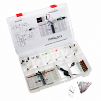
KIT EDUCATION PROPELLER
Manufacturer
Parallax Inc
Series
Propeller™r
Type
MCUr
Specifications of 32305
Contents
Propeller DIP Plus Kit, Prop Plug, PE Kit Project Parts, Breadboards and Storage Box
Product
Microcontroller Accessories
Lead Free Status / RoHS Status
Contains lead / RoHS non-compliant
For Use With/related Products
P8X32A
For Use With
130-32000 - KIT PROPELLER EDU PROJECT PARTS130-32305 - KIT PROPELLER DIP PLUS122-32000 - MANUAL PROPELLER
Lead Free Status / RoHS Status
Lead free / RoHS Compliant, Contains lead / RoHS non-compliant


The Propeller Communication window will appear briefly and display the progress. If it closes after
the “Verifying EEPROM” message, then the download was successful. If instead an error window
opens that reads “EEPROM programming error...”, refer to Troubleshooting entry (8) on page 12.
I/O Pin Tests
If you are inheriting this platform from a student who has already taken the class you are starting, it is
especially important to take some time now to confirm all the I/O pins are functioning correctly, both
as outputs and inputs. We will use the LED circuit to test each of the I/O pins’ output function on the
Propeller’s left side (P0 to P15). Since they all send the same signal as P3, each one should make the
LED circuit blink. After that, the pushbutton can be iteratively rewired to different I/O pins on the
right. PushbuttonLedTest.spin has to be modified and downloaded to the propeller to test each wiring
change. Once the left side has been tested as outputs and the right as inputs, the circuits can be
swapped so that the left side can be tested as inputs and the right side as outputs. If any of these tests
indicate that an I/O pin is faulty, refer to Troubleshooting entry (10) on page 12.
Open PushbuttonLedTest.spin into the Propeller Tool, or type it in. If you type, be careful to
indent each line exactly as shown.
Click the Propeller Tool’s Run menu and select Compile Current → Load EEPROM (F11).
Verify that the LED flashes on/off rapidly, at 10 Hz.
Press and hold the pushbutton down, and verify that the LED flashes slower, at only 4 Hz.
If everything worked as anticipated, go on to I/O Pin Tests below. If it did not work, go to
Troubleshooting entry (9) on page 12.
Use the wire connecting P3 to probe P0 through P15. Each I/O pin should cause the LED
circuit to blink the same way it does when it’s connected to P3.
Unplug the pushbutton wire at P18, and plug it into P16.
Change the
Run the modified program and verify that a pushbutton connected to P16 still controls the
LED frequency.
Repeat this procedure for P17, P19, P20, and so on, up through P27. Using F10 to download
to RAM instead of EEPROM will make this go faster.
Disconnect the battery, and remove the pushbutton and LED test circuits from the board.
Reconnect the battery and Propeller plug.
Change the
Change the
Download the modified program.
Disconnect the battery, then rebuild the test circuits on opposite sides of the board from
what’s shown in Figure 5. The pushbutton should be connected to P13, and the LED should
be used to probe I/O pins from P16 to P27.
Reconnect the battery. The LED frequency should again be controlled by the pushbutton.
Repeat the output tests for P16 to P27 and the input tests for P0 to P15.
Also use the LED to probe the positive supply rails on the right side of the board.
You can download PushbuttonLedTest.spin from the Propeller Education Kit product page at
www.parallax.com. Then, simply drag and drop it onto the Propeller Tool’s Edit Pane to open it.
Copyright © Parallax Inc. ● PE Platform Setup v1.0 ● 11/2/2006 ● Page 10 of 12
CON
CON
PUSHBUTTON
directive
directives
directive from 18 to 13.
PUSHBUTTON
LEDs_START
from 18 to 16.
and
LEDs_END
from 0 and 15 to 16 and 27.
Related parts for 32305
Image
Part Number
Description
Manufacturer
Datasheet
Request
R


Part Number:
Description:
Microcontroller Modules & Accessories DISCONTINUED BY PARALLAX
Manufacturer:
Parallax Inc

Part Number:
Description:
BOOK UNDERSTANDING SIGNALS
Manufacturer:
Parallax Inc
Datasheet:


Part Number:
Description:
COMPETITION RING FOR SUMOBOT
Manufacturer:
Parallax Inc
Datasheet:


Part Number:
Description:
TEXT INFRARED REMOTE FOR BOE-BOT
Manufacturer:
Parallax Inc
Datasheet:
Part Number:
Description:
BOARD EXPERIMENT+LCD NX-1000
Manufacturer:
Parallax Inc
Datasheet:

Part Number:
Description:
CONTROLLER 16SERVO MOTOR CONTROL
Manufacturer:
Parallax Inc
Datasheet:

Part Number:
Description:
BASIC STAMP LOGIC ANALYZER
Manufacturer:
Parallax Inc
Datasheet:

Part Number:
Description:
IC MCU 2K FLASH 50MHZ SO-18
Manufacturer:
Parallax Inc
Datasheet: