AT91RM3400-DK Atmel, AT91RM3400-DK Datasheet - Page 11
AT91RM3400-DK
Manufacturer Part Number
AT91RM3400-DK
Description
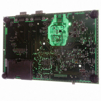
KIT DEV FOR AT91RM3400
Manufacturer
Atmel
Series
AT91SAM Smart ARMr
Type
MCUr
Datasheets
1.AT91RM3400-DK.pdf
(461 pages)
2.AT91RM3400-DK.pdf
(2 pages)
3.AT91RM3400-DK.pdf
(25 pages)
Specifications of AT91RM3400-DK
Contents
Evaluation Board, Software and Documentation
Processor To Be Evaluated
AT91RM3400
Data Bus Width
32 bit
Interface Type
RS-232, USB
For Use With/related Products
AT91RM3400
Lead Free Status / RoHS Status
Contains lead / RoHS non-compliant


4.1
AT91RM3400 Development Kit User Guide
Configuration
Straps and
Jumper Settings
Table 4-1 gives details on configuration straps and jumper settings on the AT91RM3400
development board and their default settings.
Table 4-1. Configuration Straps and Jumper Settings
Designation
S10
S11
S12
S13
S14
S15
S16
S17
S18
S1
S2
S4
S5
S6
S7
S8
S9
Default
Setting
Closed
Closed
Closed
Closed
Closed
Closed
Closed
Closed
Closed
Closed
Closed
Closed
Closed
Closed
Closed
Open
Open
Feature
The thermistor input of MAX17J7 (MN2) is tied to GND.
The guard ring is connected to GND.
The PA20/DCD1/TIA2 PIO line is connected to the LED (DS4)
The PB9/NPCS2/RD1 PIO line is connected to the buzzer (LS1)
Chip select AFF_CS is connected to the LCD panel.
The PB27/DTXD/IRQ3 PIO line is connected to the READY/BUSY
of the Serial DataFlash (MN9).
The Write Protect signal is not active for the DataFlash (MN9).
The PA8/TWCK/PCK3 PIO line is connected to the EEPROM clock
(MN10).
The PA7/TWD/PCK2 PIO line is connected to the EEPROM I/O line
(MN10).
The PA3/NPCS0/PCK1 is not connected to the serial DataFlash
chip select (MN9).
The ADC_CS PIO line is connected to the Analog-to Digital
Converter chip select.
The TD2/IRQ2/PB6 PIO line is connected to the Analog-to-Digital
Converter End of Conversion signal.
Analog-to-Digital Converter V
The PA4/NPCS1 PIO line is connected to the LCD panel.
The PA30/DXRD PIO line is connected to the DBGU receive signal
The PA14/RXD1 PIO line is connected to the USART1 read
signal.
The PA17/CTS1/TIOB0 PIO line is connected to the USB CNX
signal.
Configuration Straps
REF
PIO line is connected to GND.
Section 4
Rev. 6106A–ATARM–09/04
4-1
Related parts for AT91RM3400-DK
Image
Part Number
Description
Manufacturer
Datasheet
Request
R

Part Number:
Description:
DEV KIT FOR AVR/AVR32
Manufacturer:
Atmel
Datasheet:

Part Number:
Description:
INTERVAL AND WIPE/WASH WIPER CONTROL IC WITH DELAY
Manufacturer:
ATMEL Corporation
Datasheet:
Part Number:
Description:
Low-Voltage Voice-Switched IC for Hands-Free Operation
Manufacturer:
ATMEL Corporation
Datasheet:
Part Number:
Description:
MONOLITHIC INTEGRATED FEATUREPHONE CIRCUIT
Manufacturer:
ATMEL Corporation
Datasheet:
Part Number:
Description:
AM-FM Receiver IC U4255BM-M
Manufacturer:
ATMEL Corporation
Datasheet:
Part Number:
Description:
Monolithic Integrated Feature Phone Circuit
Manufacturer:
ATMEL Corporation
Datasheet:
Part Number:
Description:
Multistandard Video-IF and Quasi Parallel Sound Processing
Manufacturer:
ATMEL Corporation
Datasheet:
Part Number:
Description:
High-performance EE PLD
Manufacturer:
ATMEL Corporation
Datasheet:
Part Number:
Description:
8-bit Flash Microcontroller
Manufacturer:
ATMEL Corporation
Datasheet:
Part Number:
Description:
2-Wire Serial EEPROM
Manufacturer:
ATMEL Corporation
Datasheet: