AT91EB55 Atmel, AT91EB55 Datasheet - Page 14
AT91EB55
Manufacturer Part Number
AT91EB55
Description
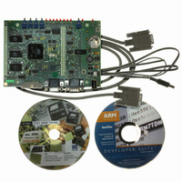
KIT EVAL FOR ARM AT91M55800A
Manufacturer
Atmel
Series
AT91SAM Smart ARMr
Type
MCUr
Datasheet
1.AT91EB55.pdf
(40 pages)
Specifications of AT91EB55
Contents
Evaluation Board, Cable, Power Jack, CD-ROM
For Use With/related Products
AT91M55800A
Lead Free Status / RoHS Status
Contains lead / RoHS non-compliant
Available stocks
Company
Part Number
Manufacturer
Quantity
Price


1709C–ATARM–28-Apr-05
The On-board Software
3.3
3.4
3-2
Programmed
Default Memory
Mapping
The Angel Debug
Monitor
When no buttons are pressed:
! Branch at address 0x01006000
! The Angel Debug Monitor starts from this address by recopying itself in external
The following table defines the mapping defined by the boot program.
Table 3-1. Memory Map
The Boot Software Program and FTS and are in sectors 0 and 1 of the Flash device.
Sectors 3 to 7 support the Angel Debug Monitor
Sector 24 at address 0x01100000 must be programmed with a boot sequence to be
debugged. This sector can be mapped at address 0x01000000 (or 0x0 after a reset)
when the jumper JP1 is in the USER position.
The Angel Debug Monitor is located in the flash from 0x01006000 up to 0x0100FFFF.
The boot program starts it if no button is pressed.
When Angel starts, it recopies itself in SRAM in order to run faster. The SRAM used by
Angel is from 0x02020000 to 0x0203FFFF, i.e., the highest half part of the SRAM.
The Angel on the AT91EB55 can be upgraded regardless of the version programmed on
it.
Note:
Part Name
U1
U2 - U3
SRAM
If the debugger is started through ICE while the Angel monitor is on, the
Advanced Interrupt Controller (AIC) and the USART channel are enabled.
Start Address
0x01000000
0x02000000
End Address
0x011FFFFF
0x0203FFFF
AT91EB55 Evaluation Board User Guide
Size
2-Mbyte
256-Kbyte
Device
Flash AT49BV162A
SRAM
Related parts for AT91EB55
Image
Part Number
Description
Manufacturer
Datasheet
Request
R

Part Number:
Description:
DEV KIT FOR AVR/AVR32
Manufacturer:
Atmel
Datasheet:

Part Number:
Description:
INTERVAL AND WIPE/WASH WIPER CONTROL IC WITH DELAY
Manufacturer:
ATMEL Corporation
Datasheet:
Part Number:
Description:
Low-Voltage Voice-Switched IC for Hands-Free Operation
Manufacturer:
ATMEL Corporation
Datasheet:
Part Number:
Description:
MONOLITHIC INTEGRATED FEATUREPHONE CIRCUIT
Manufacturer:
ATMEL Corporation
Datasheet:
Part Number:
Description:
AM-FM Receiver IC U4255BM-M
Manufacturer:
ATMEL Corporation
Datasheet:
Part Number:
Description:
Monolithic Integrated Feature Phone Circuit
Manufacturer:
ATMEL Corporation
Datasheet:
Part Number:
Description:
Multistandard Video-IF and Quasi Parallel Sound Processing
Manufacturer:
ATMEL Corporation
Datasheet:
Part Number:
Description:
High-performance EE PLD
Manufacturer:
ATMEL Corporation
Datasheet:
Part Number:
Description:
8-bit Flash Microcontroller
Manufacturer:
ATMEL Corporation
Datasheet:
Part Number:
Description:
2-Wire Serial EEPROM
Manufacturer:
ATMEL Corporation
Datasheet: