DM164123 Microchip Technology, DM164123 Datasheet - Page 14
DM164123
Manufacturer Part Number
DM164123
Description
KIT MANAGEMENT SYSTEM PICDEM
Manufacturer
Microchip Technology
Series
PICDEM™r
Type
MCUr
Specifications of DM164123
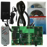
Contents
PICDEM™ System Management PCB, PICkit™ Serial Analyzer, 2 CDs, Power Supply and IDE
Silicon Manufacturer
Microchip
Core Architecture
PIC
Core Sub-architecture
PIC16
Features
MCLR Reset Line And Switch , In-Circuit Serial Programming, I2C Thermal Management Control
Silicon Core Number
PIC16F
Silicon Family Name
PIC16F8xxx
Kit Contents
Board, Serial Analyzer, Batt, Power Supply, CDs, Guides
Rohs Compliant
Yes
Lead Free Status / RoHS Status
Not applicable / Not applicable
For Use With/related Products
PIC16F886
Lead Free Status / RoHS Status
Lead free / RoHS Compliant, Not applicable / Not applicable


PICDEM™ System Management User’s Guide
1.5
DS41304B-page 10
QUICK START GUIDE
1.4.3
A resistor is used as a heating element to generate heat near the MCP9700 tempera-
ture sensor to simulate a thermal system. To activate the heating element, set the
CTRL line (RA3) high. Once, the heating element is active, the ON LED will light up. In
order to operate the heating element, JP200, heater enable jumper, must be in place.
1.4.4
The PICDEM™ System Management Board is scribed and can be separated into two
separate boards.
The fan control board contains the connectors for two, three and four-wire fans in addi-
tion to the control, power and ground lines for the heating element and temperature
sensor, as well as the fan drive circuitry.
The main board contains the PIC16F866, power input, push-buttons, LEDs, battery
backup circuit and connectors that break out the fan control, temperature sensor and
heating element pins. These elements can be used in conjunction with the prototyping
area for development.
The PICDEM™ System Management Board is preloaded with demonstration firmware.
The board must be configured as described in this section in order to use the
demonstration program. For details on firmware, please review the System
Management presentation included on the CD-ROM.
Board Setup
1. Connect the 3-wire fan to the 3-wire fan connector labeled “3-wire”.
2. Place the JP201 jumper on the bottom setting, connecting “TACH” to the middle
3. Connect the J200 jumper to allow the heating element to be turned on.
4. Plug the PICkit Serial Analyzer into the PICDEM System Management Board on
5. Plug the PICkit Serial Analyzer USB cable into a compatible PC.
Board Power-Up
Connect the provided +12V power supply to J100.
1.5.1
1. Insert the included PICDEM System Management CD into the CD drive.
2. Run the installation software for the PICDEM System Management GUI
3. Run the System Management program (start <Programs<Microchip System
Within this screen there are several tabs that allow control and monitoring of various
functions.
The heating element will be very hot when on. Do not activate the heating ele-
ment unless the fan is running. Always disconnect JP200 after use and allow
the heating element to cool.
pin.
the pins marked “PICkit Serial” (P104).
(D:\Setup\Setup.exe).
Management Board).
Heating Element
Board Options
Demonstration Program
WARNING
© 2007 Microchip Technology Inc.
Related parts for DM164123
Image
Part Number
Description
Manufacturer
Datasheet
Request
R

Part Number:
Description:
Manufacturer:
Microchip Technology Inc.
Datasheet:
Part Number:
Description:
Manufacturer:
Microchip Technology Inc.
Datasheet:
Part Number:
Description:
Manufacturer:
Microchip Technology Inc.
Datasheet:
Part Number:
Description:
Manufacturer:
Microchip Technology Inc.
Datasheet:
Part Number:
Description:
Manufacturer:
Microchip Technology Inc.
Datasheet:
Part Number:
Description:
Manufacturer:
Microchip Technology Inc.
Datasheet:
Part Number:
Description:
Manufacturer:
Microchip Technology Inc.
Datasheet:
Part Number:
Description:
Manufacturer:
Microchip Technology Inc.
Datasheet: