DM240011 Microchip Technology, DM240011 Datasheet - Page 21
DM240011
Manufacturer Part Number
DM240011
Description
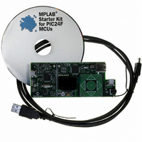
KIT STARTER MPLAB FOR PIC24F MCU
Manufacturer
Microchip Technology
Series
MPLAB®r
Type
MCUr
Datasheet
1.DM240011.pdf
(42 pages)
Specifications of DM240011
Contents
Board, Cable, CD
Processor To Be Evaluated
PIC24F
Data Bus Width
16 bit
Interface Type
USB
Silicon Manufacturer
Microchip
Core Architecture
PIC
Core Sub-architecture
PIC24
Silicon Core Number
PIC24F
Silicon Family Name
PIC24FJxxGBxxx
Kit Contents
Board Cables CD Docs
Lead Free Status / RoHS Status
Lead free / RoHS Compliant
For Use With/related Products
PIC24F
Lead Free Status / Rohs Status
Lead free / RoHS Compliant
Available stocks
Company
Part Number
Manufacturer
Quantity
Price
Company:

Part Number:
DM240011
Manufacturer:
Microchip Technology
Quantity:
135
Company:
Part Number:
DM240011
Manufacturer:
MICROCHIP
Quantity:
12 000


© 2008 Microchip Technology Inc.
3.2.4
In this configuration, the starter kit has been programmed with a debugged,
stand-alone USB embedded host application; programmer/debugger support is not
needed. Because of the absence of a host PC, this configuration can truly be
considered a “stand-alone” operation.
Since there are no connections to a host PC, the starter kit board must be physically
modified to accept an external power supply. A regulated power supply providing 5 V
must be available.
Make the following modifications to the starter kit (Figure 3-3):
1. Install posts at the V
2. Populate the site for R16 (adjacent to the V
3. Supply +5 V
FIGURE 3-3:
If the modifications are done correctly, and power is connected correctly, the green
Target Power LED (D4) is lit. The starter kit also goes through its power-on sequence
before LED1 displays the “PIC24 Starter Kit” main menu.
When configured for external power operation, the programmer/debugger function is
essentially disabled. To re-enable these functions, disconnect the external power from
the board and remove the resistor/jumper from R16 before connecting the USB cable
to J1.
If you externally power V
disconnect any USB cables connected to a computer or hub. Otherwise, damage to the
PC’s USB port or the external hub may result.
R16 (populate)
V
BUS
and GND connections on the board.
+5.0V
Embedded Host, Release Mode (Stand-Alone Mode)
DC
and ground connections from the external power supply to the
STARTER KIT MODIFICATIONS FOR STAND-ALONE POWER
OPERATION
M
BUS
BUS
via the test point, please make certain that you first
and GND test points on the board.
CAUTION
Ground
BUS
test point) with a 0 ohm resistor.
DS51725A-page 17
DC
Related parts for DM240011
Image
Part Number
Description
Manufacturer
Datasheet
Request
R

Part Number:
Description:
Manufacturer:
Microchip Technology Inc.
Datasheet:
Part Number:
Description:
Manufacturer:
Microchip Technology Inc.
Datasheet:
Part Number:
Description:
Manufacturer:
Microchip Technology Inc.
Datasheet:
Part Number:
Description:
Manufacturer:
Microchip Technology Inc.
Datasheet:
Part Number:
Description:
Manufacturer:
Microchip Technology Inc.
Datasheet:
Part Number:
Description:
Manufacturer:
Microchip Technology Inc.
Datasheet:
Part Number:
Description:
Manufacturer:
Microchip Technology Inc.
Datasheet:
Part Number:
Description:
Manufacturer:
Microchip Technology Inc.
Datasheet: