DM240001 Microchip Technology, DM240001 Datasheet - Page 29
DM240001
Manufacturer Part Number
DM240001
Description
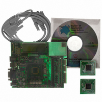
BOARD DEMO PIC24/DSPIC33/PIC32
Manufacturer
Microchip Technology
Series
Explorer 16 100-pinr
Type
MCUr
Specifications of DM240001
Contents
Explorer 16 Dev Board, PIC24FJ128GA010 and dsPIC33FJ256GP710 PIM Modules
Processor To Be Evaluated
PIC 24 and dsPIC33
Data Bus Width
16 bit
Interface Type
RS-232
Silicon Manufacturer
Microchip
Core Architecture
PIC, DsPIC
Core Sub-architecture
PIC24, DsPIC33
Silicon Core Number
PIC24F, DsPIC33F
Rohs Compliant
Yes
Lead Free Status / RoHS Status
Lead free / RoHS Compliant
For Use With/related Products
dsPIC30, dsPIC33, PIC32, PIC24FJ, PIC24HJ
For Use With
AC164127-5 - BOARD GRAPH LCD CNTLR PICTAILAC164127-3 - BOARD DAUGHTER GRAPHIC PICTAILAC164127 - BRD DAUGHT GRAPHIC PICTAIL PLUS
Lead Free Status / Rohs Status
Lead free / RoHS Compliant
Available stocks
Company
Part Number
Manufacturer
Quantity
Price
Company:

Part Number:
DM240001
Manufacturer:
MICROCHIP
Quantity:
12 000


Explorer 16 Development Board User’s Guide
3.3
DS51589A-page 25
dsPIC33F TUTORIAL PROGRAM OPERATION
The dsPIC33F tutorial program is made up of five simple processes which continuously
execute on the dsPIC33FJ256GP710 device:
• Real-Time Clock (RTC) using Timer1
• A/D conversion of Potentiometer (R6)
• A/D volts to Hex conversion
• Hex to Decimal conversion (for LCD display)
• LCD Update
The time of day and A/D conversion values are continually updated and displayed on
the LCD. The program demonstrates the basic code to initialize Timer1, enable the
Timer1 oscillator for RTC operation, and initialize the A/D for single channel conversion
of potentiometer, RP5. The LCD is driven via the port pins. The program flow is shown
in Figure 3-2.
In addition to the tutorial, the Explorer 16 CD also provides code examples to demon-
strate higher level processing requirements, such as DMA, digital filters and Fast
Fourier Transforms (FFT). See Code Example 2 on the CD for more information.
3.3.1
The simple tutorial program initializes the A/D module for 12-bit mode with
auto-sampling and conversion of the potentiometer connected to pin AN5 and initial-
izes the respective interrupt. The A/D module continually samples and converts the
potentiometer signal (0 to 3.3 VDC) on analog channel, AN5. When a conversion is
complete, an interrupt is generated and the result in the ADCBUF0 register is copied
into a temporary variable, temp1. The adc_lcd_update flag is then asserted and the
A/D Interrupt Flag, AD1IF (IFS0<13>), is cleared.
The program exits the Interrupt Service Routine and re-enters the main program loop.
The variable, adc_lcd_update , is evaluated in the main loop to determine if there is
a new A/D conversion value which can be converted and displayed on the LCD.
The primary code modules associated with the operation of the ADC module and
display are:
• init_ADC.c
• isr_ADC.c
• advolts.c
• hexdec.c
3.3.2
The tutorial program also supports a Real-Time Clock demo. Timer1 is initialized with
interrupts enabled and the external 32.768 kHz oscillator is enabled. Within the Timer1
Interrupt Service Routine (once every second), the variables, hours, minutes and
seconds, are updated, the flag variable, rtc_lcd_update, is asserted and the
Timer1 Interrupt Flag, T1IF (IFS0<3>), is cleared.
The program exits the Interrupt Service Routine and re-enters the main program loop.
The variable, rtc_lcd_update, is evaluated in the main loop to determine if there is
a new time of day value which can be converted and displayed on the LCD.
The primary code modules associated with the operation of the Timer1 module and
display are:
• init_timer1.c
• isr_timer1.c
• hexdec.c
Voltmeter
Real-Time Clock
© 2005 Microchip Technology Inc.
Related parts for DM240001
Image
Part Number
Description
Manufacturer
Datasheet
Request
R

Part Number:
Description:
Manufacturer:
Microchip Technology Inc.
Datasheet:
Part Number:
Description:
Manufacturer:
Microchip Technology Inc.
Datasheet:
Part Number:
Description:
Manufacturer:
Microchip Technology Inc.
Datasheet:
Part Number:
Description:
Manufacturer:
Microchip Technology Inc.
Datasheet:
Part Number:
Description:
Manufacturer:
Microchip Technology Inc.
Datasheet:
Part Number:
Description:
Manufacturer:
Microchip Technology Inc.
Datasheet:
Part Number:
Description:
Manufacturer:
Microchip Technology Inc.
Datasheet:
Part Number:
Description:
Manufacturer:
Microchip Technology Inc.
Datasheet: