ATEVK1101 Atmel, ATEVK1101 Datasheet - Page 8
ATEVK1101
Manufacturer Part Number
ATEVK1101
Description
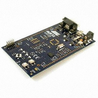
KIT DEV/EVAL FOR AVR32 AT32UC3B
Manufacturer
Atmel
Series
AVR®32r
Type
MCUr
Specifications of ATEVK1101
Contents
Evaluation Board, Software and Documentation
Kit Contents
ATEVK1101 Demo Board, CD-ROM
Supported Devices
AT32UC3B
Mcu Supported Families
AT32UC3B MCU
Rohs Compliant
Yes
For Use With/related Products
AT32UC3B064, 0128, 0256, 164, 1128, 1256
Lead Free Status / RoHS Status
Lead free / RoHS Compliant
Other names
Q3463470
Available stocks
Company
Part Number
Manufacturer
Quantity
Price
Company:

Part Number:
ATEVK1101
Manufacturer:
Atmel
Quantity:
135


6.2.2 Flash User Page
6.3 Boot Process
8
Flash and ISP specification
The bootloader uses the flash User page to store the I/O conditions that determine which of the
USB DFU ISP and the application to start at the end of the boot process.
Table 6-4. Bootloader Flash User Page Configuration Word
The default value of the bootloader flash User page configuration word is:
•
•
•
i.e. the ISP will be activated when
•
•
Refer to section 7.3 “Customizing the ISP Configuration Word” to compute a value of the boot-
loader configuration word from a given set of ISP_IO_COND_PIN and ISP_IO_COND_LEVEL
values.
After reset, the boot process starts at 80000000h:
•
•
•
Last 32
Bits of the
Flash User
Page
7:0
15:8
16
31:17
929E1424h for AVR UC3 A0, A1,
0x929E2A9E for AVR UC3 A3
929E0D6Bh for AVR UC3 B0, B1,
the joystick is pressed on EVK1100 or EVK1101 at reset,
the SW2 button is pressed on EVK1104 at reset.
BOD is enabled with reset if the ISP_BOD_EN GP fuse bit is 1.
If the ISP_FORCE GP fuse bit is 1, the USB DFU ISP is immediately started.
If the ISP_FORCE GP fuse bit is 0:
Name
ISP_CRC8
ISP_IO_COND_PIN
ISP_IO_COND_LEVEL
ISP_BOOT_KEY
Description
CRC8 on the bootloader User page configuration
word with polynomial:
P(X) = X
This CRC is used to check the validity of this
configuration word.
The GPIO pin number to test during the boot
process to know which of the USB DFU ISP and the
application to start. E.g., to select PX16 (i.e. QFP144
pin 61 and the GPIO pin 88) on AT32UC3A0512,
this bit-field has to be set to 88.
Possible values are:
- 0 to 109 for AVR UC3 A0 QFP144;
- 0 to 69 for AVR UC3 A1 QFP100;
- 0 to 109 for AVR UC3 A3 QFP144 or BGA144
- 0 to 43 for AVR UC3 B0 QFP64;
- 0 to 27 for AVR UC3 B1 QFP48.
Active level of ISP_IO_COND_PIN that the
bootloader will consider as a request for starting the
USB DFU ISP: 0 for GPIO low level, 1 for GPIO high
level.
Boot key = 494Fh. This key is used to identify the
word as meaningful for the bootloader.
8
+X
2
+X+1.
7745C–AVR32–05/09
Related parts for ATEVK1101
Image
Part Number
Description
Manufacturer
Datasheet
Request
R

Part Number:
Description:
DEV KIT FOR AVR/AVR32
Manufacturer:
Atmel
Datasheet:

Part Number:
Description:
INTERVAL AND WIPE/WASH WIPER CONTROL IC WITH DELAY
Manufacturer:
ATMEL Corporation
Datasheet:
Part Number:
Description:
Low-Voltage Voice-Switched IC for Hands-Free Operation
Manufacturer:
ATMEL Corporation
Datasheet:
Part Number:
Description:
MONOLITHIC INTEGRATED FEATUREPHONE CIRCUIT
Manufacturer:
ATMEL Corporation
Datasheet:
Part Number:
Description:
AM-FM Receiver IC U4255BM-M
Manufacturer:
ATMEL Corporation
Datasheet:
Part Number:
Description:
Monolithic Integrated Feature Phone Circuit
Manufacturer:
ATMEL Corporation
Datasheet:
Part Number:
Description:
Multistandard Video-IF and Quasi Parallel Sound Processing
Manufacturer:
ATMEL Corporation
Datasheet:
Part Number:
Description:
High-performance EE PLD
Manufacturer:
ATMEL Corporation
Datasheet:
Part Number:
Description:
8-bit Flash Microcontroller
Manufacturer:
ATMEL Corporation
Datasheet:
Part Number:
Description:
2-Wire Serial EEPROM
Manufacturer:
ATMEL Corporation
Datasheet: