DM163022 Microchip Technology, DM163022 Datasheet - Page 17
DM163022
Manufacturer Part Number
DM163022
Description
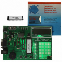
BOARD DEMO PICDEM-2 PLUS
Manufacturer
Microchip Technology
Type
MCUr
Specifications of DM163022
Contents
Board, CD, Sample Part
Processor To Be Evaluated
PIC 16 and PIC 18
Interface Type
RS-232
Silicon Manufacturer
Microchip
Core Architecture
PIC
Core Sub-architecture
PIC16, PIC18
Silicon Core Number
PIC16F, PIC18F
Silicon Family Name
PIC16F8xx, PIC18F4xxx
Rohs Compliant
NA
Lead Free Status / RoHS Status
Lead free / RoHS Compliant
For Use With/related Products
PICDEM 2 Plus
Lead Free Status / Rohs Status
Lead free / RoHS Compliant
Other names
DM163022R
DM163022R
DM163022R
Available stocks
Company
Part Number
Manufacturer
Quantity
Price
Company:

Part Number:
DM163022
Manufacturer:
Microchip Technology
Quantity:
135
Company:
Part Number:
DM163022-1
Manufacturer:
MICROCHIP
Quantity:
12 000


3.1
© 2007 Microchip Technology Inc.
TUTORIAL PROGRAM OPERATION
The tutorial program is preprogrammed into the sample device. (For example, the file
p16demo.hex is for a PIC16 device and p18demo.hex is for a PIC18 device.) This
program also is on the included CD-ROM program disk for user reference. (If the
sample device has been reprogrammed with another program, the tutorial may be
reprogrammed into the device.)
For a flowchart of the tutorial program, see Figure 3-1.
For detailed information on the PICDEM 2 Plus hardware, please refer to Appendix A.
The tutorial program is made up of four components, which are individually displayed
on the LCD.
1. Voltmeter
2. Buzzer
3. Temperature
This mode uses the A/D module to measure the voltage of the R16 pot and
display a voltage between 0.00V and 5.00V on the LCD.
Voltage is continually updated until the mode is exited by pressing RB0.
This mode turns on the Piezo buzzer, using the CCP1 module I/O pin, RC2.
The period and duty cycle of the CCP1 frequency can be changed while the
buzzer is on. The changes in period and duty cycle are recognized immediately
in the buzzer tone.
- To change the period and/or the duty cycle, press RB0 under the “Buzzer”
- To change the duty cycle, press RA4 once and the cursor will now flash over
This mode uses a TC74 thermal sensor to measure ambient temperature in
Celsius and then display that temperature on the LCD. Communication between
the PIC
is exited by pressing RB0. This mode contains code that will write to the external
on-board EEPROM. Every two seconds, the code will write to a defined
EEPROM address and store the current temperature in that address.
menu.
The buzzer will then sound off with the default setting of 80h for the period and
duty cycle. The cursor will flash over the period’s first digit, indicating that the
PR2 register is ready to be incremented.
the duty cycle’s first digit, indicating it is now ready to increment the CCPR1L
register.
The next press of RA4 will exit the buzzer function.
®
MCU and sensor is accomplished using the MSSP module. This mode
Chapter 3. Tutorial
PICDEM™ 2 PLUS USER’S GUIDE
DS51275D-page 13
Related parts for DM163022
Image
Part Number
Description
Manufacturer
Datasheet
Request
R

Part Number:
Description:
Manufacturer:
Microchip Technology Inc.
Datasheet:
Part Number:
Description:
Manufacturer:
Microchip Technology Inc.
Datasheet:
Part Number:
Description:
Manufacturer:
Microchip Technology Inc.
Datasheet:
Part Number:
Description:
Manufacturer:
Microchip Technology Inc.
Datasheet:
Part Number:
Description:
Manufacturer:
Microchip Technology Inc.
Datasheet:
Part Number:
Description:
Manufacturer:
Microchip Technology Inc.
Datasheet:
Part Number:
Description:
Manufacturer:
Microchip Technology Inc.
Datasheet:
Part Number:
Description:
Manufacturer:
Microchip Technology Inc.
Datasheet: