DM320001 Microchip Technology, DM320001 Datasheet
DM320001
Specifications of DM320001


Related parts for DM320001

DM320001 Summary of contents
Page 1
... Microchip Technology Inc. PIC32MX Starter Kit User’s Guide DS61144B ...
Page 2
... PowerInfo, PowerMate, PowerTool, REAL ICE, rfLAB, Select Mode, Smart Serial, SmartTel, Total Endurance, UNI/O, WiperLock and ZENA are trademarks of Microchip Technology Incorporated in the U.S.A. and other countries. SQTP is a service mark of Microchip Technology Incorporated in the U.S.A. All other trademarks mentioned herein are property of their respective companies. ...
Page 3
... Introduction ................................................................................................... 31 4.2 Hardware Features ....................................................................................... 31 Appendix A. PIC32MX Starter Kit Schematics A.1 Introduction .................................................................................................. 33 A.2 Development Board Block Diagram ............................................................. 33 A.3 Starter Kit Board Schematics ....................................................................... 33 Index ............................................................................................................................. 39 Worldwide Sales and Service .................................................................................... 40 © 2007 Microchip Technology Inc. PIC32MX STARTER KIT Table of Contents USER’S GUIDE DS61144B-page iii ...
Page 4
... NOTES: DS61144B-page iv © 2007 Microchip Technology Inc. ...
Page 5
... Chapter 4. “PIC32MX Starter Kit Hardware” provides a more detailed descrip- tion of the features of the hardware included in the PIC32MX Starter Kit. • Appendix A. “PIC32MX Starter Kit Schematics” provides a block diagram and detailed schematics of the PIC32MX Starter Kit. © 2007 Microchip Technology Inc. PIC32MX STARTER KIT Preface NOTICE TO CUSTOMERS USER’ ...
Page 6
... Click the Power tab Press <Enter>, <F1> #define START autoexec.bat c:\mcc18\h _asm, _endasm, static -Opa+, -Opa 0xFF, ‘A’ , where file can be any file.o valid filename mcc18 [options] file [options] errorlevel {0|1} var_name [, var_name...] void main (void) { ... } © 2007 Microchip Technology Inc. ...
Page 7
... Microchip consultant program member listings • Business of Microchip – Product selector and ordering guides, latest Microchip press releases, listings of seminars and events; and listings of Microchip sales offices, distributors and factory representatives © 2007 Microchip Technology Inc. PIC32MX.txt . This web www.microchip.com DS61144B-page 3 ...
Page 8
... Technical support is available through the web site DOCUMENT REVISION HISTORY Revision A (October 2007) This is the initial release of the PIC32MX Starter Kit User’s Guide. Revision B (October 2007) Removed confidential status. DS61144B-page 4 , click on Customer www.microchip.com ® Plus, PICkit™ 1 and http://support.microchip.com © 2007 Microchip Technology Inc. ® ...
Page 9
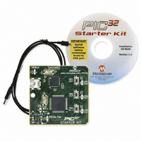
... Chapter 1. Introducing the PIC32MX Starter Kit 1.1 INTRODUCTION Thank you for purchasing the Microchip Technology PIC32MX Starter Kit. This kit provides a low-cost, modular development system for Microchip’s new line of 32-bit microcontrollers. The Starter Kit comes pre-loaded with demonstration software for the user to explore the new features of the PIC32MX ...
Page 10
... Three push-button switches for user-defined inputs 9. Three user-defined indicator LEDs 10. Connector for connecting various expansion boards (on the underside of board) For additional details on these features, refer to Chapter 4. “PIC32MX Starter Kit Hard- ware”. FIGURE 1- DS61144B-page 6 PIC32MX STARTER KIT DEMO BOARD LAYOUT © 2007 Microchip Technology Inc. ...
Page 11
... PIC32MX Starter Kit CD-ROM for future reference. All project files have been included, so that the code may be used directly to restore a PIC32MX to its original state (i.e., if the sample device has been reprogrammed with another program you can use the tutorial code as a platform for further experimentation. © 2007 Microchip Technology Inc. DS61144B-page 7 ...
Page 12
... NOTES: DS61144B-page 8 © 2007 Microchip Technology Inc. ...
Page 13
... An available USB port powered USB hub • CD-ROM drive • Windows XP (The PIC32MX Starter Kit has not been tested on Microsoft Windows 2000 © 2007 Microchip Technology Inc. PIC32MX STARTER KIT ® ® or Microsoft Vista™ operating systems) USER’S GUIDE ® ...
Page 14
... Section 2.5 “Starting the Tutorial Project” on page 14. If you did not, continue to the next page for instructions about how to connect the board and install the device driver. DS61144B-page 10 setup.exe INSTALLING THE PIC32 STARTER KIT BOARD . © 2007 Microchip Technology Inc. ...
Page 15
... When the USB cable is connected, the “Found New Hardware Wizard” dialog box opens, as shown in Figure 2-2. When asked whether to install the software automatically or install from a list or specific location, select “Install software automatically” and click Next. FIGURE 2-2: © 2007 Microchip Technology Inc. FOUND NEW HARDWARE WIZARD DS61144B-page 11 ...
Page 16
... When it is done, click Next. FIGURE 2-3: 3. When the wizard finds the driver, a dialog box regarding Windows Logo testing opens, as shown in Figure 2-4. Click Continue Anyway. FIGURE 2-4: DS61144B-page 12 HARDWARE WIZARD WINDOWS LOGO TESTING © 2007 Microchip Technology Inc. ...
Page 17
... The next window (Figure 2-5) indicates that the installation of the software for the Starter Kit is complete. Click Finish. FIGURE 2-5: © 2007 Microchip Technology Inc. COMPLETING DEVICE DRIVER INSTALLATION DS61144B-page 13 ...
Page 18
... Kit from the menu bar. If that sequence fails to find the project, check the driver installation, as well as the connections between the hardware and the PC. ® FIGURE 2-6: MPLAB IDE WORKSPACE DS61144B-page 14 c:\Program Files\Microchip\ (or browse to file path you used when you installed the © 2007 Microchip Technology Inc. ’, ‘ ’ and .c .h ...
Page 19
... From the menu bar of the main MPLAB IDE window, click Project>Make. The build Output window displays, as shown in Figure 2-7. Observe the progress of the build. When the “BUILD SUCCEEDED” message displays, you are ready to program the device. FIGURE 2-7: © 2007 Microchip Technology Inc. BUILD OUTPUT WINDOW DS61144B-page 15 ...
Page 20
... Click Yes. FIGURE 2-9: The Output window (Figure 2-10) tracks the progress of the output. A “Done” entry indicates that the programming of the device is complete. FIGURE 2-10: DS61144B-page 16 PROGRAM DEVICE TOOL BAR PROGRAMMING WARNING WINDOW OUTPUT WINDOW © 2007 Microchip Technology Inc. ...
Page 21
... The Starter Kit tutorial demonstrates a simple application. The program responds according to the user input menu. The program prints the available menu choices to the Starter Kit Output window in the MPLAB IDE. The program flow is shown in Figure 2-12. © 2007 Microchip Technology Inc. DEBUG WINDOW DS61144B-page 17 ...
Page 22
... In itia lize isp “ t” ‘x ’ ild ice ‘e ’ ‘E ’ ice ‘r’ ‘R ’ ice ‘o ’ ‘O ’ ice ‘g ’ ‘G ’ ice ‘x’ ‘X ’ isp ice lid © 2007 Microchip Technology Inc. ...
Page 23
... Type your choice into the Enter Information to be Returned box, and click Send. The program responds according to the menu entry. Watch the LEDs on the Starter Kit board. If your entry is incorrect, the LEDs will toggle once. © 2007 Microchip Technology Inc. . db_utils.h ...
Page 24
... NOTES: DS61144B-page 20 © 2007 Microchip Technology Inc. ...
Page 25
... Task 4, Add Files to Your Project on page 25. Task 5, Confirm the Configuration Settings on page 27. Task 6, Build the Project on page 28. Task 7, Program the Device on page 29. Task 8, Run the Program on page 30. © 2007 Microchip Technology Inc. PIC32MX STARTER KIT USER’S GUIDE is assumed in the following instructions). C:\MyProject ...
Page 26
... The Project Wizard Step One: window is displayed, as shown in Figure 3-1. FIGURE 3-1: 1.5. From the “Device” drop-down list, select “PIC32MX360F512L”. 1.6. Click Next. The Project Wizard Step Two: dialog box opens, as shown in Figure 3-2. DS61144B-page 22 SELECTING THE DEVICE © 2007 Microchip Technology Inc. ...
Page 27
... With “MPLAB 32 LINK Object Linker (pic30-ld.exe)” selected in the “Toolsuite Contents” box, click Browse... and navigate to: “c:\Program Files\Microchip\MPLAB C32\bin\pic32-Id.exe”. 2.5. Click Next to continue. The Project Wizard Step Three: dialog opens, as shown in Figure 3-3. © 2007 Microchip Technology Inc. SELECTING THE TOOLSUITE ”. ) DS61144B-page 23 ...
Page 28
... In the “Create New Project File” field, click Browse... and navigate to “C:\MyProject\BlinkLED” to place your project in the you created before starting these instructions. 3.2. Click Next to continue. The Project Wizard Step Four: dialog opens, as shown in Figure 3-4. DS61144B-page 24 NAMING YOUR PROJECT folder that MyProject © 2007 Microchip Technology Inc. ...
Page 29
... You can see a new empty file. 4.4. Click File>Save As... and save this file as ‘ this case, the 4.5. Now copy the source code provided in Example 3-1 to the © 2007 Microchip Technology Inc. ADDING FILES TO THE PROJECT ’ files have been created the workspace file and BlinkLED.mcp blinkLED ...
Page 30
... Turn off LED2 on startup */ mPORTDSetPinsDigitalOut(BIT_2);/* Make RD0 (LED2) as output */ while( for ever { for(i=0; i<200000; i++);// put a delay mPORTDToggleBits(BIT_0);/* turn ON LED0 */ for(i=0; i<200000; i++);// put a delay mPORTDToggleBits(BIT_1);/* turn ON LED1 */ for(i=0; i<200000; i++);// put a delay mPORTDToggleBits(BIT_2);/* turn ON LED2 */ }; return 0; } DS61144B-page 26 © 2007 Microchip Technology Inc. ...
Page 31
... Typical configuration settings for the Starter Kit are shown in Figure 3-6. Note: The Configuration settings can also be embedded in the source file. See the MPLAB C32 C Compiler User’s Guide for more information. © 2007 Microchip Technology Inc. file to the source directory, as blinkLED.c ADDING SOURCE FILES ...
Page 32
... Click Project>Make from the menu bar of the main MPLAB IDE window. The build Output window displays (Figure 3-7). 6.2. Observe the progress of the build. When the “BUILD SUCCEEDED” message displays, you are ready to program the device. FIGURE 3-7: DS61144B-page 28 BUILD OUTPUT WINDOW © 2007 Microchip Technology Inc. ...
Page 33
... Click Yes. FIGURE 3-9: The Output window (Figure 3-10) tracks the progress of the output. “Done” signals that the programming of the device is complete. FIGURE 3-10: © 2007 Microchip Technology Inc. PROGRAM DEVICE WINDOW PROGRAMMING WARNING WINDOW OUTPUT WINDOW DS61144B-page 29 ...
Page 34
... Click Debugger>Run from the menu bar of the MPLAB IDE or click the Run icon (the turquoise triangle) on the Debug Tool Bar, as indicated in Figure 3-11, to run the new program. FIGURE 3-11: The Starter Kit LEDs blink to indicate that the program is running successfully. DS61144B-page 30 RUN THE PROGRAM © 2007 Microchip Technology Inc. ...
Page 35
... The PIC32MX Starter Kit currently uses the JTAG pins of the PIC32MX device for programming and debugging. At the time of initial release, the PIC18LF4550 is loaded with USB bootloader firmware, which permits easy upgrades of connectivity firmware over the USB connection. © 2007 Microchip Technology Inc. PIC32MX STARTER KIT USER’S GUIDE DS61144B-page 31 ...
Page 36
... Modular Expansion Connector The PIC32MX Starter Kit demo board has been designed with a 120-pin modular expansion interface, which allows the board to provide basic generic functionality now, as well as easy extendability to new technologies as they become available. DS61144B-page 32 © 2007 Microchip Technology Inc. ...
Page 37
... STARTER KIT BOARD SCHEMATICS Figure A-2. PIC32MX CPU Figure A-3. PIC18LF4550 Debug CPU Figure A-4. Application Board Connector Figure A-5. Switches and LEDs Figure A-6. Power Supply © 2007 Microchip Technology Inc. PIC32MX STARTER KIT Power Supply +3.3V ICSP™ JTAG PIC32MX360F512L USER’ ...
Page 38
... DS61144B-page 34 © 2007 Microchip Technology Inc. ...
Page 39
... Microchip Technology Inc. DS61144B-page 35 ...
Page 40
... FIGURE A-4: PIC32MX SCHEMATIC, SHEET (APPLICATION BOARD CONNECTOR) DS61144B-page 36 © 2007 Microchip Technology Inc. ...
Page 41
... FIGURE A-5: PIC32MX SCHEMATIC, SHEET (SWITCHES AND LEDS) © 2007 Microchip Technology Inc. DS61144B-page 37 ...
Page 42
... FIGURE A-6: PIC32MX SCHEMATIC, SHEET (POWER SUPPLY) DS61144B-page 38 © 2007 Microchip Technology Inc. ...
Page 43
... Language Toolsuite ................................................. 23 Last Schematic ........................................................ 38 LEDs Power................................................................ 11 M Microchip Internet Web Site ....................................... 3 MPLAB ....................................................................... 7 MPLAB IDE Simulator, Editor User’s Guide............... 3 © 2007 Microchip Technology Inc. PIC32MX STARTER KIT USER’S Index P PIC32MX Layout 32-bit microcontroller ................................... 6 Connector for expansion boards.................. 6 Debug indicator LED.................................... 6 On-board crystal ...
Page 44
... Fax: 886-3-572-6459 Taiwan - Kaohsiung Tel: 886-7-536-4818 Fax: 886-7-536-4803 Taiwan - Taipei Tel: 886-2-2500-6610 Fax: 886-2-2508-0102 Thailand - Bangkok Tel: 66-2-694-1351 Fax: 66-2-694-1350 © 2007 Microchip Technology Inc. EUROPE Austria - Wels Tel: 43-7242-2244-39 Fax: 43-7242-2244-393 Denmark - Copenhagen Tel: 45-4450-2828 Fax: 45-4485-2829 France - Paris Tel: 33-1-69-53-63-20 ...