AS5145 AB austriamicrosystems, AS5145 AB Datasheet - Page 13
AS5145 AB
Manufacturer Part Number
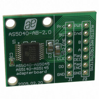
AS5145 AB
Description
BOARD ADAPTER AS5145
Manufacturer
austriamicrosystems
Specifications of AS5145 AB
Sensor Type
Magnetic, Rotary Position
Sensing Range
360°
Interface
Serial
Voltage - Supply
5V
Embedded
No
Utilized Ic / Part
AS5145
Lead Free Status / RoHS Status
Lead free by exemption / RoHS compliant by exemption
Sensitivity
-


AS5145
Data Sheet - D e t a i l e d D e s c r i p t i o n
8.1.1 Synchronous Serial Interface (SSI)
Figure 5. Synchronous Serial Interface with Absolute Angular Position Data
If CSn changes to logic low, Data Out (DO) will change from high impedance (tri-state) to logic high and the read-out will be initiated.
Data Content
D11:D0 absolute angular position data (MSB is clocked out first)
OCF (Offset Compensation Finished), logic high indicates the finished Offset Compensation Algorithm
COF (Cordic Overflow), logic high indicates an out of range error in the CORDIC part. When this bit is set, the data at D11:D0 is invalid. The
absolute output maintains the last valid angular value.
This alarm may be resolved by bringing the magnet within the X-Y-Z tolerance limits.
LIN (Linearity Alarm), logic high indicates that the input field generates a critical output linearity.
When this bit is set, the data at D11:D0 may still be used, but can contain invalid data. This warning may be resolved by bringing the magnet
within the X-Y-Z tolerance limits.
Even Parity bit for transmission error detection of bits 1…17 (D11…D0, OCF, COF, LIN, MagINC, MagDEC)
Placing the magnet above the chip, angular values increase in clockwise direction by default.
Data D11:D0 is valid, when the status bits have the following configurations:
Table 8. Status Bit Outputs
Note: MagInc=MagDec=1 is only recommended in YELLOW mode
www.austriamicrosystems.com/AS5145
CSn
CLK
DO
After a minimum time t
Each subsequent rising CLK edge shifts out one bit of data.
The serial word contains 18 bits, the first 12 bits are the angular information D[11:0], the subsequent 6 bits contain system information,
about the validity of data such as OCF, COF, LIN, Parity and Magnetic Field status (increase/decrease).
A subsequent measurement is initiated by a “high” pulse at CSn with a minimum duration of tCSn.
OCF
t
DO active
1
t
CLK FE
T
CLK/2
1
D11
CLK FE
D10
COF
t
, data is latched into the output shift register with the first falling edge of CLK.
DO valid
0
D9
D8
Angular Position Data
D7
D6
D5
LIN
0
8
D4
Revision 1.11
D3
(see Table 9)
D2
D1
Mag INC
0
0
1
1
D0
OCF COF LIN
Status Bits
Mag DEC
Mag
INC
0
1
0
1
DEC
Mag
18
Even
PAR
t
DO Tristate
t
CSn
Even checksum of bits
t
CLK FE
Parity
1:15
1
D11
13 - 36
Related parts for AS5145 AB
Image
Part Number
Description
Manufacturer
Datasheet
Request
R

Part Number:
Description:
BOARD DEMO AS5145
Manufacturer:
austriamicrosystems
Datasheet:

Part Number:
Description:
IC ENCODER PROG 12-BIT 16-SSOP
Manufacturer:
austriamicrosystems
Datasheet:
Part Number:
Description:
IC ENCODER PROG 12-BIT 16-SSOP
Manufacturer:
austriamicrosystems
Datasheet:
Part Number:
Description:
12 Bit Programmable Magnetic Rotary Encoder
Manufacturer:
austriamicrosystems
Datasheet:
Part Number:
Description:
IC SWITCH QUAD SPST 14-TSSOP
Manufacturer:
austriamicrosystems
Datasheet:
Part Number:
Description:
IC SWITCH QUAD SPST 14-TSSOP
Manufacturer:
austriamicrosystems
Datasheet:
Part Number:
Description:
IC AMP AUDIO MONO 1.8W 10-MSOP
Manufacturer:
austriamicrosystems
Datasheet:
Part Number:
Description:
IC AMP AUDIO MONO 1.8W 10-MSOP
Manufacturer:
austriamicrosystems
Datasheet:
Part Number:
Description:
IC AMP AUDIO MONO 1.8W 10-MSOP
Manufacturer:
austriamicrosystems
Datasheet:
Part Number:
Description:
IC AMP AUD 1.8W 3DB GAIN 10-MSOP
Manufacturer:
austriamicrosystems
Datasheet:
Part Number:
Description:
IC DRIVER LED 8-DIGIT 24-SOIC
Manufacturer:
austriamicrosystems
Datasheet:
Part Number:
Description:
IC DRIVER LED 8-DIGIT 24-SOIC
Manufacturer:
austriamicrosystems
Datasheet:
Part Number:
Description:
IC, LINE/SPEAKER PHONE CIRCUIT, SOIC-28
Manufacturer:
austriamicrosystems
Datasheet:
Part Number:
Description:
IC MULTI-STANDARD CMOS TELEPHONE SOIC-28
Manufacturer:
austriamicrosystems
Datasheet:
Part Number:
Description:
IC MULTI-STANDARD CMOS TELEPHONE SOIC-28
Manufacturer:
austriamicrosystems
Datasheet: