AS5045 AB austriamicrosystems, AS5045 AB Datasheet - Page 4

AS5045 AB
Manufacturer Part Number
AS5045 AB
Description
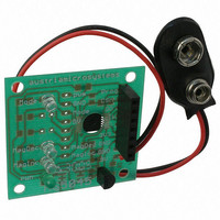
BOARD ADAPTER AS5045
Manufacturer
austriamicrosystems
Specifications of AS5045 AB
Sensor Type
Magnetic, Rotary Position
Sensing Range
360°
Interface
Serial
Voltage - Supply
9V
Embedded
No
Utilized Ic / Part
AS5045
Lead Free Status / RoHS Status
Lead free by exemption / RoHS compliant by exemption
Sensitivity
-
AS5045
Data Sheet
5 Pinout
5.1 Pin Configuration
Figure 2. Pin Configuration SSOP16
5.2 Pin Description
Table 1 shows the description of each pin of the standard SSOP16 package (Shrink Small Outline Package, 16
leads, body size: 5.3mm x 6.2mmm; see Figure 2).
Pins 7, 15 and 16 supply pins, pins 3, 4, 5, 6, 13 and 14 are for internal use and must not be connected.
Pins 1 and 2 MagINCn and MagDECn are the magnetic field change indicators (magnetic field strength increase or
decrease through variation of the distance between the magnet and the device). These outputs can be used to
detect the valid magnetic field range. Furthermore those indicators can also be used for contact-less push-button
functionality.
Pin 6 Mode allows switching between filtered (slow) and unfiltered (fast mode). This pin must be tied to VSS or
VDD5V, and must not be switched after power up. See chapter 8 Mode Input Pin.
Pin 8 Prog is used to program the zero-position into the OTP (see chapter 11.1 Zero Position Programming).
This pin is also used as digital input to shift serial data through the device in Daisy Chain configuration,
(see chapter 8.2 Daisy Chain Mode).
Pin 11 Chip Select (CSn; active low) selects a device within a network of AS5045 encoders and initiates serial data
transfer. A logic high at CSn puts the data output pin (DO) to tri-state and terminates serial data transfer. This pin is
also used for alignment mode (Figure 14) and programming mode (Figure 10).
Pin 12 PWM allows a single wire output of the 10-bit absolute position value. The value is encoded into a pulse width
modulated signal with 1µs pulse width per step (1µs to 4096µs over a full turn). By using an external low pass filter,
the digital PWM signal is converted into an analog voltage, making a direct replacement of potentiometers possible.
Table 1. Pin Description
www.austriamicrosystems.com
Pin
1
2
3
4
MagINCn
MagDECn
NC
NC
Symbol
DO_OD
DO_OD
-
-
Type
MagDECn
MagINCn
Prog_DI
Magnet Field Magnitude INCrease; active low, indicates a distance reduction
between the magnet and the device surface. See Table 5
Magnet Field Magnitude DECrease; active low, indicates a distance increase
between the device and the magnet. See Table 5
Must be left unconnected
Must be left unconnected
Mode
VSS
NC
NC
NC
2
5
1
3
4
6
7
8
Revision 1.7
16
15
14
13
12
10
11
9
Description
VDD5V
NC
PWM
VDD3V3
NC
CSn
CLK
DO
4 – 33


