AS5045 AB austriamicrosystems, AS5045 AB Datasheet - Page 5

AS5045 AB
Manufacturer Part Number
AS5045 AB
Description
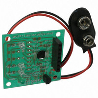
BOARD ADAPTER AS5045
Manufacturer
austriamicrosystems
Specifications of AS5045 AB
Sensor Type
Magnetic, Rotary Position
Sensing Range
360°
Interface
Serial
Voltage - Supply
9V
Embedded
No
Utilized Ic / Part
AS5045
Lead Free Status / RoHS Status
Lead free by exemption / RoHS compliant by exemption
Sensitivity
-
AS5045 12-BIT PROGRAMMABLE MAGNETIC ROTARY ENCODER
Adapter PCB Operation Manual
Output modes:
a) PWM output:
no additional components are necessary. Once the power supply has been applied, the angle information is
available at the PWM pin (pin1 of J1)
b) Absolute angle information
To access the 12-bit absolute angle information, an external microcontroller must be connected as shown in
Figure 5. Make sure that the controller is able to drive the CSn pin with the connected pulldown resistor (R7). If
necessary, remove this resistor.
The clock rate can be as high as 1MHz. There is no minimum clock rate. Data can also be clocked manually.
The digital I/O's of the AS5045 are buffered by VDD5V, therefore the digital I/O's of the controller should be at the
same voltage level (see power supply options table).
d) Magnetic field strength status; Pushbutton function
no additional components are necessary. The two open-drain outputs MagInc and MagDec (pins 8 and 7 of J1)
will turn on/off as the magnetic field (distance between magnet and chip surface) changes. When both outputs are
on, the magnetic field is not within the recommended range (see datasheet).
Programming (zapping) the Chip.
For programming the AS5045, 3 digital signals are required: CSn, Prog and CLK (see datasheet). For permanent
writing, VPROG must be elevated to 7.5V during the programming cycle.
For immediate programming, this PCB can be connected directly to the AS5045 demo board (available
separately), where all the programming timings are generated by the onboard microcontroller.
AS5045 adapter PCB layout and component placement:
The PCB has several connection options. All required
pins are accessible via the two 100mil- connectors J1
and J2.
These connectors are 600mil apart, which allows them to
be soldered to a wide 16-pin DIL IC socket for easier
access or ribbon cable connection.
Furthermore, J2 (pins 3..9) fit to the AS5045 demo board
and allow this PCB to be used as external encoder.
The hole in the PCB underneath the chip allows
centering of a 6mm diameter magnet.
The 6 LEDs and voltage regulators are optional.
Minimum required components are C4 (1µF) and R7
(0…4k7).
AS5045 adapter board: top view
Layout: Bottom View
Layout: Bottom Components
Revision A.02, 14-Mar-07
www.austriamicrosystems.com
Page 5 of 12


