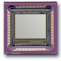
CYII5SM1300-EVAL Cypress Semiconductor Corp, CYII5SM1300-EVAL Datasheet - Page 24

CYII5SM1300-EVAL
Manufacturer Part Number
CYII5SM1300-EVAL
Description
BOARD EVAL IMG SENS IBIS5-B-1300
Manufacturer
Cypress Semiconductor Corp
Datasheet
1.CYII5FM1300-EVAL.pdf
(35 pages)
Specifications of CYII5SM1300-EVAL
Sensor Type
CMOS Imaging, Monochrome
Sensing Range
1.3 Megapixel
Interface
Parallel/Serial
Sensitivity
106 fps
Voltage - Supply
3 V ~ 4.5 V
Embedded
No
Utilized Ic / Part
IBIS5-B-1300
Lead Free Status / RoHS Status
Contains lead / RoHS non-compliant
Lead Free Status / RoHS Status
Lead free / RoHS Compliant, Contains lead / RoHS non-compliant
Rolling Shutter Operation
The integration of the light in the image sensor is done during
readout of the other lines.
The only difference with synchronous shutter is that the
TIME_OUT pin is used to indicate when the Y_SYNC pulse for
the right Y-shift-register (reset Y-shift register) is generated. This
loads the right Y-shift-register with the pointer loaded in register
YR_REG. The Y_SYNC pulse for the left Y-shift register (read
Y-shift register) is generated with Y_START.
The INT_TIME register defines how many lines to count before
the Y_SYNC of the right Y-shift-register is generated, hence
defining the integration time. See also
on page 18 for a detailed description of the rolling shutter
operation.
T
register(INT_TIME)
Note For normal operation the values of the YL_REG and
YR_REG registers are equal.
Document #: 38-05710 Rev. *H
int
Integration time [# lines] = register(NROF_LINES) –
INT_TIME Register (11:0)
Figure 26. Rolling Shutter Operation
Figure 27. Windowing in X-Direction
Windowing in X-Direction
An X_LOAD pulse overrides the internal X_SYNC signal, loading
a new X-pointer (stored in the X_REG register) into the
X-shift-register.
The X_LOAD pulse must appear on the falling edge of
SYS_CLOCK and remain high for two SYS_CLOCK cycles
overlapping two rising edges of SYS_CLOCK. The new
X-pointer is loaded on one of the two rising edges of
SYS_CLOCK.
The available time to upload the register is T
from the previous register load to the rising edge of X_LOAD. It
depends on the settling time of the register and the X-decoder.
Table 25. T
The actual time to load the register itself depends on the
interface mode that is used. The parallel interface is the fastest.
Parallel interface
Serial 3 Wire
Interface Mode
load
for Different Interfaces
1 (about 40 SYS_CLOCK cycles)
16 (at 2.5 MHz data rate)
T
load
(µs)
CYII5SM1300AB
load
Page 24 of 35
; it is defined
[+] Feedback


