FHS 40-P KIT 8-1P LEM USA Inc, FHS 40-P KIT 8-1P Datasheet
FHS 40-P KIT 8-1P
Specifications of FHS 40-P KIT 8-1P


Related parts for FHS 40-P KIT 8-1P


FHS 40-P KIT 8-1P Summary of contents
Page 1
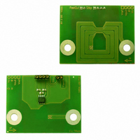
... User guide for FHS 40-P Current Transducer FHS 40-P Kit 8 (G2.00.23.107.0) Evaluation PCB Connectors Pin-OUT The board has two single row connectors J1 and J2. • The four pin one (J1) makes possible to supply the board and access to the output voltage easily. It has the following pin-out: ...
Page 2
Thermal Capability The enclosed evaluation PCB has tracks with thickness of 70 µm. The dimensions of the tracks drawn on the evaluation PCB lead to some limitations on the maximum continuous current which can go through the PCB track. Remark: ...
Page 3
The following figures should be taken into account to avoid overheating: (T primary track = 115 °C) Maxi rms current I [ Typical primary current for a maximum track temperature of 115°C (natural ...
Page 4
Connect then the primary between pins I Features Magnetic field sensitivity Current sensitivity Measuring range Frequency range L insertion Isolation characteristics Rms voltage for AC isolation test, 50-60 Hz, 1 min Impulse withstand voltage 1.2/50 µs Creepage/Clearance ...
Page 5
Application example According to EN 50178 and IEC 61010-1 standards and following conditions: • Rated isolation voltage 300 V (IEC 61010-1) • Reinforced isolation • Over voltage category OV III • Pollution degree PD1 • Non-uniform field Safety This transducer ...