FHS 40-P KIT 5-1P LEM USA Inc, FHS 40-P KIT 5-1P Datasheet - Page 7
FHS 40-P KIT 5-1P
Manufacturer Part Number
FHS 40-P KIT 5-1P
Description
FHS 40 PCB KIT 16/55A
Manufacturer
LEM USA Inc
Specifications of FHS 40-P KIT 5-1P
Sensor Type
Current Sensor
Sensing Range
±55A
Interface
Analog
Sensitivity
36.3 mV/A
Voltage - Supply
4.75 V ~ 5.25 V
Embedded
No
Utilized Ic / Part
FHS 40
Lead Free Status / RoHS Status
Lead free / RoHS Compliant
Other names
398-1073


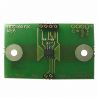
Typical connection diagram and ground plane
Values of the electrical data given page 3 are according to the following connection diagram.
Careful design of the PCB is needed to ensure minimum disturbance by surrounding currents and external fields.
C
The maximum capacitor value allowed on V
The maximum capacitor value allowed on V
A positive output voltage V
1/8 end. V
If the pin V
An internally generated reference voltage of 2.5 V with a source resistance of 200 Ω is available on the pin V
on this pin may be forced externally with a voltage in the range 1.5 - 2.8 V. The output voltage V
value of V
V
internal pull-down whose resistance is 500 kΩ). It should be connected to 0 V if not used.
Connect V
Minisens can be directly mounted above the PCB track in which the current to be measured flows (see kit 4, for example).
100727/10
STANDBY
1
to C
3
should be connected to a low impedance so that capacitive coupling from adjacent tracks does not disturb it (there is an
should be mounted as close as possible to the pins.
REF
SFast
STANDBY
OUTFast
in both positive and negative polarities.
is negative when V
is not used, it should be connected only to a small solder pad. Coupling to other tracks should be minimized.
to the same voltage as V
conductor
Primary
LEM reserves the right to carry out modifications on its transducers, in order to improve them, without prior notice.
S
is obtained with a current (I
I
P
Figure 6: Typical connection diagram (C
S
is positive.
isolation
barrier
C
to activate the Standby mode. V
OUT
OUTFast
is 18 nF. It is recommended to use 4.7 nF.
V
is 330 pF.
STANDBY
STANDBY
0 V
5, 6
7
P
) flowing under Minisens from the pin 4/5 end of the package to the pin
+5V
V
•
C
4
0 V
V
3
OUTFast
C
V
V
3
OUT
REF
REF
8
1
2
1
should not be forced in Standby mode.
= C
•
•
3
C
C
= 47 nF, C
1
2
V
SFast
2
S
= 4.7 nF)
is limited to approximately the
FHS 40-P/SP600
V
S
REF
. The voltage
0 - 100A
www.lem.com
Page 7/18
Related parts for FHS 40-P KIT 5-1P
Image
Part Number
Description
Manufacturer
Datasheet
Request
R

Part Number:
Description:
FHS 40 PCB KIT 30/78A
Manufacturer:
LEM USA Inc
Datasheet:

Part Number:
Description:
FHS 40 PCB KIT 16/30A
Manufacturer:
LEM USA Inc
Datasheet:

Part Number:
Description:
FHS 40 PCB W/JUMPER KIT 10/10A
Manufacturer:
LEM USA Inc
Datasheet:

Part Number:
Description:
FHS 40 PCB KIT 5/16A
Manufacturer:
LEM USA Inc
Datasheet:

Part Number:
Description:
FHS 40 PCB KIT 5/11A
Manufacturer:
LEM USA Inc
Datasheet:


Part Number:
Description:
Wide Beam Lens
Manufacturer:
FRAEN
Datasheet:

Part Number:
Description:
Wide Beam Lens
Manufacturer:
FRAEN
Datasheet:

Part Number:
Description:
SENSOR CURRENT 200A TH
Manufacturer:
LEM USA Inc
Datasheet:


Part Number:
Description:
TRANSFORM CURR 100A SPLIT CORE
Manufacturer:
LEM USA Inc
Datasheet:

Part Number:
Description:
TRANSFORM CURRENT 50A SPLIT CORE
Manufacturer:
LEM USA Inc
Datasheet:

Part Number:
Description:
SENSOR CURRENT 20A 5V UNI SMD
Manufacturer:
LEM USA Inc
Datasheet:

Part Number:
Description:
SENSOR CURRENT 15A 5V UNI SMD
Manufacturer:
LEM USA Inc
Datasheet:

Part Number:
Description:
SENSOR CURRENT 10A 5V UNI SMD
Manufacturer:
LEM USA Inc
Datasheet: