E1106 Atmel, E1106 Datasheet - Page 15
E1106
Manufacturer Part Number
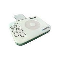
E1106
Description
BOARD EVALUATION FOR QT1106-ISG
Manufacturer
Atmel
Specifications of E1106
Sensor Type
*
Sensing Range
*
Interface
*
Sensitivity
*
Voltage - Supply
*
Embedded
*
Utilized Ic / Part
*
Interface Type
USB
Lead Free Status / RoHS Status
Lead free / RoHS Compliant
For Use With/related Products
QT1106
Other names
E1106AT


6.4 Rsns Resistors
Series resistors R
in-line with the electrode connections and are used to limit
electrostatic discharge (ESD) currents and to suppress radio
frequency interference (RFI). For most applications R
be in the range 4.7k to 33k each. In a few applications
with low loading on the sense keys the value may be up to
100k .
Although these resistors may be omitted, the device may
become susceptible to external noise or RFI. For details of
how to select these resistors see the Application Note
AN-KD02, downloadable from the Quantum website
http://www.qprox.com
Application Notes).
6.5 Thermal Stability
The QT1106 can operate with or without the wheel/slider and
supports up to seven keys. Channels not fitted with a sense
capacitor will automatically be switched off during calibration.
For better thermal stability while operating with only one key,
it is best to fit a sense capacitor of the same type and value
for another spare key channel, in another burst group.
Additionally a small value Cx (~5pF COG) should be fitted to
simulate electrode capacitance.
The Cx value required for best thermal stability can be
obtained by matching the burst lengths of the key channel
and the dummy channel. The burst lengths of the channels
can be captured on an oscilloscope via the coin method, as
described in the Application note AN-KD02 (see Section 6.4).
This provides a stable reference for increased thermal
stability.
Lq
SNS
(R
(go to the Support tab and click
SNSA
1...R
SNSA
3, R
SNSB
1...R
SNSB
SNSB
7) are
will
15
6.6 Power Supply
The power supply can range from 2.8 to 5.0 volts. If this
fluctuates slowly with temperature, the device will track and
compensate for these changes automatically with only minor
changes in sensitivity. If the supply voltage drifts or shifts
quickly, the drift compensation mechanism will not be able to
keep up, causing sensitivity anomalies or false detections.
The QT1106 power supply should be locally regulated using
a three-terminal device, to between 2.8V and 5.0V. If the
supply is shared with another electronic system, care should
be taken to ensure that the supply is free of digital spikes,
sags, and surges, all of which can cause adverse effects.
For proper operation a 0.1µF, or greater, bypass capacitor
must be used between Vdd and Vss; the bypass capacitor
should be routed with very short tracks to the QT1106's Vss
and Vdd pins.
6.7 PCB Layout and Construction
Refer to the Application Note AN-KD02 ‘Secrets of a
Successful QTouch Design’, downloadable from the
Quantum web site
tab and click Application Notes) for information related to
layout and construction matters. Downloadable example CAD
files for wheels and sliders can also be found on the website)
The sensing channels used for the individual keys can be
implemented as per AN-KD02.
http://www.qprox.com
QT1106_8IR0.07_0907
(go to the Support
Related parts for E1106
Image
Part Number
Description
Manufacturer
Datasheet
Request
R

Part Number:
Description:
BOARD EVAL FOR QT110 TOUCH SENSR
Manufacturer:
Atmel
Datasheet:

Part Number:
Description:
DEV KIT FOR AVR/AVR32
Manufacturer:
Atmel
Datasheet:

Part Number:
Description:
INTERVAL AND WIPE/WASH WIPER CONTROL IC WITH DELAY
Manufacturer:
ATMEL Corporation
Datasheet:
Part Number:
Description:
Low-Voltage Voice-Switched IC for Hands-Free Operation
Manufacturer:
ATMEL Corporation
Datasheet:
Part Number:
Description:
MONOLITHIC INTEGRATED FEATUREPHONE CIRCUIT
Manufacturer:
ATMEL Corporation
Datasheet:
Part Number:
Description:
AM-FM Receiver IC U4255BM-M
Manufacturer:
ATMEL Corporation
Datasheet:
Part Number:
Description:
Monolithic Integrated Feature Phone Circuit
Manufacturer:
ATMEL Corporation
Datasheet:
Part Number:
Description:
Multistandard Video-IF and Quasi Parallel Sound Processing
Manufacturer:
ATMEL Corporation
Datasheet:
Part Number:
Description:
High-performance EE PLD
Manufacturer:
ATMEL Corporation
Datasheet:
Part Number:
Description:
8-bit Flash Microcontroller
Manufacturer:
ATMEL Corporation
Datasheet:
Part Number:
Description:
2-Wire Serial EEPROM
Manufacturer:
ATMEL Corporation
Datasheet: