RD3172MMA7455L Freescale Semiconductor, RD3172MMA7455L Datasheet
RD3172MMA7455L
Specifications of RD3172MMA7455L
Available stocks


Related parts for RD3172MMA7455L

RD3172MMA7455L Summary of contents
Page 1
DRM103 Designer Reference Manual Devices Supported: MMA7361L MMA7455L MMA7660FC Document Number: DRM103 Rev. 2 11/2009 ...
Page 2
Safety of Radio Frequency Energy The manufacturer has evaluated the transmitter for safe operation for uncontrolled use in the general population. The measured power density under the threshold established by the FCC and is not required ...
Page 3
... Clocking Options for the MC13213 ................................................................................... 31 3.3.9 LED Indicator .................................................................................................................... 31 3.3.10 Power Supply .................................................................................................................. 31 3.4 New PCB Revision 00288_04 ....................................................................................................... 32 3.5 Bill of Materials .............................................................................................................................. 33 3.6 ZSTAR3 Schematic - revision 00288_02 ....................................................................................... 36 3.7 ZSTAR3 Schematic - Revision 00288_04 ..................................................................................... 37 4.1 Board Overview ............................................................................................................................. 39 Freescale Semiconductor Chapter 1 Introduction Chapter 2 Chapter 3 Chapter 4 USB Stick Board Description DRM103, Rev. 2 ...
Page 4
... Switch to Bootloader Procedure ....................................................................................... 55 5.6.2 Bootloading Procedure ..................................................................................................... 56 5.7 Tri-application Software on the USB Stick ..................................................................................... 58 5.7.1 CDC - Virtual Serial Port Application ................................................................................ 59 5.7.2 HID - Mouse Application ................................................................................................... 59 5.7.3 HID - Keyboard Application ............................................................................................... 60 5.7.4 Application Switching ........................................................................................................ 61 4 Chapter 5 Software Design Description ........................................................................... 45 Zcommand Description ........................................................................ 45 DRM103, Rev. 2 Freescale Semiconductor ...
Page 5
... Orientation Detection Demo Application ............................................................ 89 7.2.11.2 Tap Detection Demo Application ........................................................................ 90 7.2.11.3 Power management control box of the MMA7660FC ......................................... 91 7.2.12 Freescale Web Links. ...................................................................................................... 92 7.3 The ZSTAR3 GUI Update USB Stick Software Utility .................................................................... 93 7.3.1 Update Process (Manual Start) ........................................................................................ 93 Freescale Semiconductor Chapter 6 Application Setup Chapter 7ZSTAR3 GUI Appendix A References DRM103, Rev ...
Page 6
... DRM103, Rev. 2 Freescale Semiconductor ...
Page 7
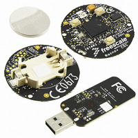
Figures The ZSTAR Demo Migration Photo (CR2032 batteries for comparison) .................................... 11 ZSTAR3 Sensor Board ............................................................................................................... 13 ZSTAR3 Block Diagram.............................................................................................................. 14 Block diagram of MMA7455L...................................................................................................... 17 Block diagram of MMA7660FC ................................................................................................... 18 ZSTAR3 Sensor Board Overview ............................................................................................... 21 Sensor Board ...
Page 8
Update Software Procedure - Step 2 .......................................................................................... 93 Update Software Procedure - Step 3 .......................................................................................... 94 Update Software Procedure - Step 4 .......................................................................................... 94 Update Software Procedure - Step 5 .......................................................................................... 95 Original Bootloader Application................................................................................................... 95 ...
Page 9
Tables Sensor Board Bill of Materials - MMA7361LT Sensor Version .................................................. 33 Sensor Board Bill of Materials - MMA7455L Sensor version ..................................................... 34 Sensor Board Bill of Materials - MMA7660FC Sensor version .................................................. 35 Original ZSTAR Commands Zcommand ZSTAR3 Main ...
Page 10
...
Page 11
... Fall, Tilt, Motion, Positioning, Shock and Vibration - for multifunctional applications. The RD3172MMA7455L / RD3172MMA7361L / RD3172MMA7660FC development tool offers robust wireless communication using the powerful, easy-to-use 2.4 GHz frequency transceiver and microcontroller in the one package MC13213. Without any changes on board, it can be made with pin to pin compatibility allowing implementation of the MC13214 for ZigBee® ...
Page 12
... Introduction 12 DRM103, Rev. 2 Freescale Semiconductor ...
Page 13
... This board is used from the older ZSTAR demo, but with new software. Both sides communicate over the RF medium utilizing the freely available lightly modified software stack Simple Media Access Control (SMAC) from Freescale. Freescale Semiconductor ZSTAR3 Wireless Sensing Triple Axis Reference Design Introduction Figure 2-1. ZSTAR3 Sensor Board DRM103, Rev ...
Page 14
... ZSTAR3 Wireless Sensing Triple Axis Reference Design Introduction 2.4GHz MC13191 HC908JW32 ZSTAR USB Stick 14 ZSTAR3 Sensor Board MC13213 MMA7361LT/ MMA7455L Figure 2-2. ZSTAR3 Block Diagram DRM103, Rev. 2 ZSTAR3 GUI Freescale Semiconductor ...
Page 15
... The MMA7361LT includes a sleep mode that makes it ideal for handheld battery powered electronics. Features: • 1.0 mm LGA-14-pin package • Low current consumption: 400 µA • Sleep mode: 3 µA • Low voltage operation: 2 3.6 V Freescale Semiconductor ZSTAR3 Wireless Sensing Triple Axis Reference Design Introduction DRM103, Rev ...
Page 16
... Programmable threshold interrupt output • Level detection for motion recognition (shock, vibration, freefall) • Single or double click (pulse) recognition • High sensitivity — 64 LSB — 64 LSB 10-bit mode 16 2 C/SPI), low power 0.8 mm low profile package capacitive DRM103, Rev. 2 Freescale Semiconductor ...
Page 17
... Robust Design, High Shocks Survivability (10,000 g) • RoHS Compliant • Environmentally Preferred Product • Low Cost Freescale Semiconductor ZSTAR3 Wireless Sensing Triple Axis Reference Design Introduction Figure 2-3. Block diagram of MMA7455L 2 C), very low power, low profile capacitive micro machined DRM103, Rev ...
Page 18
... Programmable frequency clock output for MCU • Auto-trim feature for crystal accuracy • Eliminates the need for external variable capacitors • Allows for automated production frequency calibration • 71-pin LGA package • RoHS compliant • GPIO’s 18 Figure 2-4. Block diagram of MMA7660FC DRM103, Rev. 2 Freescale Semiconductor ...
Page 19
... Asymmetric Encryption Standard (AES) — Object Code • BeeStack ZigBee Protocol Stack — ZigBee 2006 Compliant Platform — Object Code Freescale Semiconductor ZSTAR3 Wireless Sensing Triple Axis Reference Design Introduction 2 C) with 100 kbps maximum bus loading DRM103, Rev ...
Page 20
... ZSTAR3 Wireless Sensing Triple Axis Reference Design Introduction 20 DRM103, Rev. 2 Freescale Semiconductor ...
Page 21
... Crystal LED indicator Lithium battery on the opposite side Figure 3-1. ZSTAR3 Sensor Board Overview 1. This is valid for 00288_02 PCB revision (black edition). For new revision (00288_04) see chapter 3.4 New PCB Revision 00288_04. Freescale Semiconductor 1 DRM103, Rev. 2 MC13213 MMA7455L / MMA7361LT PCB antennas ...
Page 22
... This basic loop repeats 30 times per second (period is 33.333 ms) providing nearly a real-time response from the Sensor. 1. The MMA7660FC is supported by new PCB with revision code 00288_04. 22 Figure 3-2. Sensor Board Block Diagram The ZSTAR3 RF Protocol to send this data frame over the RF link DRM103, Rev. 2 MC13213 SiP - System in Antenna Package MCU + RF 1 Freescale Semiconductor ...
Page 23
... For example, in this way the analog sensor uses the ADC to read XYZ sensor values of sensor and the digital sensor uses the digital interface, but in the source code there is only one line: p_Read_Accelerometer((void*) &(accel_data[0].x)). 1. The MMA7660FC is supported by new PCB with revision code 00288_04. Freescale Semiconductor Data Buffer RF ...
Page 24
... GPIO pins controlled by software. Also the KBI interface can supports interrupt signals of used sensors. 1. This is valid for 00288_04 PCB revision (red edition). See chapter 3.4 New PCB Revision 00288_04. The old one version of PCB 00288_02 doesn’t provide external pull-up’ bus. DRM103, Rev bus , or any other Freescale Semiconductor ...
Page 25
... USB stick. The ZSTAR3 sensor board typically opens a receive window every 10th period (~333 ms) to maintain synchronization with the USB stick (Communication Master) and to receive possible control data from the master. 1. The MMA7660FC is supported by new PCB with revision code 00288_04. Freescale Semiconductor 1 DRM103, Rev. 2 ZSTAR3 Sensor Board Description ...
Page 26
... The “optional receive” feature allows huge power savings, whilst still keeping synchronization of ZSTAR3 network data from the data-receiving side. 26 Run Stop Plan next RX window TX data transmitted th loop is the receive window opened (receiver is enabled to message). More in Section 5.3, The ZSTAR3 RF Protocol DRM103, Rev. 2 Stop Doze time Sensor being measured NOT TO SCALE Freescale Semiconductor ...
Page 27
... The MMA7361L provides four further digital signals g-select, Self-test, 0g-detect and Sleep. All these pins are also routed into the microcontroller, but only the g-select and the 0g-detect are controlled by the current version of the ZSTAR3 software. Freescale Semiconductor Supply. DRM103, Rev. 2 ...
Page 28
... This is valid for 00288_02 PCB revision (black edition). For new revision (00288_04) see chapter 3.4 New PCB Revision 00288_04 and SPI. These pins are routed to general I/O pins and data, SPI data input/output DRM103, Rev module 1 Freescale Semiconductor ...
Page 29
... The three buttons (S1, S2 and S3) are connected directly to pins PTA0, PTA6 and PTA7. All these pins have internal pull-up resistors, and are part of the Keyboard Interrupt module, therefore allow a direct microcontroller wake-up from the Stop modes. 1. The MMA7660FC is supported by new PCB with revision code 00288_04. Freescale Semiconductor microcontroller module. The board are ...
Page 30
... The antenna was designed as a “smile” layout, 10.7 x 24.3 mm (420 x 960 mil), made of 1.25 mm (50 mil) wide trace of copper. The matching is provided by L1 coil. L2 and L3 coils bias the transmitter output transistors to the CT_Bias level. 30 Figure 3-6. ZSTAR3 Antenna Layout DRM103, Rev. 2 Freescale Semiconductor ...
Page 31
... MC13213 during a receive/transmit without significant VDD voltage drops. The design doesn’t have any main power switch, thus switch on is done by pressing any button on the board and switch off is done by software (Time-out, Out of range, RF protocol command). Freescale Semiconductor ™ is placed on the underside of the PCB. The DRM103, Rev ...
Page 32
... MMA7331LT: ±4g, ±12g Three Axis Low-g Analog Micromachined Accelerometer • MMA7455LT: ±8g, ±2g, ±4g Three Axis Low-g Digital Micromachined Accelerometer • MMA7660FC: ±1.5g Three Axis Low-g Digital Micromachined Accelerometer bus. MMA7660FC MMA7361L MMA7455L footprint DRM103, Rev. 2 00288_02 2 C pull-up’s resistors. These resistors Freescale Semiconductor ...
Page 33
... L2 S1, S2 C17, C18, R2 R3, U3 Freescale Semiconductor Part Manufacturer battery holder Renata CR2032 220μF/4V AVX 6.8pF TDK 100nF TDK 1μF TDK 10nF TDK 3.3nH TDK 22nH TDK Kingbright Kingbright KP-1608SEC BDM + serial N/A 16MHz NX2520SA NDK 150R TYCO switch SKRP Alps ...
Page 34
... TYCO 1K TYCO switch SKRP Alps MC13213 Freescale MMA7455L Freescale NA NA DRM103, Rev. 2 Manufacturer order code SMTU 2032-1 TAJB227M004R C1608CH1H070D C1608JB1H104K C1608JB1A105KB 232270296001 MLG1608B3N3DT MLG1608B22NJT KP-1608SEC NX2520SA 16MHz EXS00A-02940 Specification n° EXS10B-07228 RN73F1J150RBTG RN73F1J1K0BTDF SKRPADE010 (or SKRPACE010 or SKRPABE010) MC13213 MMA7455L NA Freescale Semiconductor ...
Page 35
... R2 S1, S2 C4, C13, C14 C15, C16, C17, U2 Freescale Semiconductor Part Manufacturer battery holder Renata CR2032 220μF/4V AVX 6.8pF TDK 100nF TDK 1μF TDK 3.3nH TDK 22nH TDK Kingbright Kingbright KP-1608SEC BDM + serial N/A 16MHz NX2520SA NDK 150R TYCO 1K TYCO switch SKRP ...
Page 36
... ZSTAR3 Sensor Board Description 3.6 ZSTAR3 Schematic - Revision 00288_02 Z-axis Y-axis X-axis DRM103, Rev. 2 Freescale Semiconductor ...
Page 37
... ZSTAR3 Schematic - Revision 00288_04 Z-axis Y-axis X-axis SCL/SPC SDA Freescale Semiconductor DRM103, Rev. 2 ZSTAR3 Sensor Board Description 37 ...
Page 38
... ZSTAR3 Sensor Board Description 38 DRM103, Rev. 2 Freescale Semiconductor ...
Page 39
... The USB stick board used is the same as in the original ZSTAR demo, but with new software. For more hardware details, please check the RD3152MMA7261 Reference Design manual on www.freescale.com LED Indicators MCHC908JW32 Freescale Semiconductor Figure 4-1. USB stick Board Overview DRM103, Rev. 2 PCB Antennas ...
Page 40
... For the USB stick board operation, several MCHC908JW32 hardware modules are used: USB 2.0 Full-speed (USB), Synchronous Peripheral Interface (SPI), Keyboard Interrupt (KBI) and a General Purpose Input/Output (GPIO). 40 Sensors Data PC protocol handler RF S Protocol M Handler A C Protocol. DRM103, Rev. 2 USB driver USB USB port Freescale Semiconductor ...
Page 41
... ZSTAR3 sensor board. Furthermore, a couple of new functions were added to this SMAC version. A fully detailed description of the SMAC is in the SMAC Reference Manual (SMACRM.pdf), available together with SMAC source code. Freescale Semiconductor modifications description description (over USB) implementation notes DRM103, Rev ...
Page 42
... Support for sensors (slaves) • Network main period (33.333 ms) • Data capture designed network • Identification Network number (NetNum) • Automatic/Manual selection of communication channels • Collect all RSSI (Receive Signal Strength Indicator) information on communication 42 drivers that are available for the DRM103, Rev. 2 Freescale Semiconductor ...
Page 43
... The network number in the sensor board can be cleared by pressing all the buttons together during a board wake-up sequence command from the USB stick. Packets with different Network numbers are simply ignored. This field is 16 bits long. Freescale Semiconductor Payload Data FLI SMAC Packet Structure ...
Page 44
... Sensor Board calibration data from Sensor Board accelerometer values, temperature and bandgap voltage, button levels, g-range selection List Zdata Status and optional subcommand Accelerometers values, status info none Calibration data, board info Optional return read data from ION Freescale Semiconductor ...
Page 45
... This command is used by the sensor to acknowledge successfully received USB stick subcommand. 5.3.4.3 ZSTAR3_CONNECT With this command the sensor board sends calibration data on to the USB stick. The command is also used to start communication between the sensor board and the USB stick. Freescale Semiconductor Zcommand Direction Code USB stick to Sensor Board ...
Page 46
... Each sensor board without a mechanical power switch has an implemented automatic switch off function when a 2 minute timeout overflows 4... Selected Subcommand sensor Figure 5-2. ZSTAR3_PYLON Zdata Format ZSTAR3_PYLON 2 in the sensor board and thus keep the sensor ZSTAR3_ACK DRM103, Rev. 2 Data depends on sub commands command. All these command. ZSTAR3_ACK Freescale Semiconductor 1 . ...
Page 47
... Slave (sensor board) - the sensor board software contains this state and it can support the original ZSTAR too. All sensor boards are ordered with prohibited compatibility mode, because the compatibility mode causes a lot of problems when the demo runs in the same RF space as any original ZSTAR. Freescale Semiconductor command. command. DRM103, Rev. 2 ...
Page 48
... Slave device. Slave MCU Slave MCU Slave MCU Master Tx Rx MCU SMAC Interrupts 48 ZSTAR3 RF Protocol Typical Period Figure 5-3. ZSTAR3 RF Protocol Period DRM103, Rev. 2 ZSTAR3_PYLON ZSTAR3_PYLON message from the Freescale Semiconductor ...
Page 49
... LED is brightly blinking with frequency Demo is still in broadcast mode, but it founds own ZSTAR3 network (with right NetNum) and its position/index is occupied by any other sensor. • LED is lightly blinking with frequency Demo is in run mode and it communicate with USB Stick. Freescale Semiconductor DRM103, Rev. 2 Software Design 49 ...
Page 50
... PC sends any command from a new subset of the command table. This extended information returns to the PC information resulting from individual commands. Red Blue Magenta 50 Commands. Table 5-4. Legend of Colors Legend Direction PC -> USB stick Direction USB stick -> PC, regular data Direction USB stick -> PC, extended data DRM103, Rev. 2 Section 5.4.3, Subset of Freescale Semiconductor ...
Page 51
... If a connected sensor has ZSTAR3 protocol, then the calibration data command isn’t important 5.4.2 Subset of Original ZSTAR Protocol Commands The ZSTAR3 software contains all slightly changed original ZSTAR commands. Red Blue Freescale Semiconductor Table 5-5. Original STAR Commands Extended Asynchronous Length tx/rx (B) ...
Page 52
... DRM103, Rev. 2 Answer Note Length rx (B) - Reset to 16 bit mode - Read extended 16 bits acceleration data - Return text information about ZSTAR project - Switch on sending debug information - Switch off sending debug information - Debug auto calibration command - Read Receive Strength Signal Indicators Freescale Semiconductor 1 ...
Page 53
... ZSTAR version burst sensor mask, ‘x’, connected sensors ‘X’ mask ‘X’ ‘x’ ‘z’ ‘Z’ Freescale Semiconductor Length tx/rx ( ‘A’ 2,1 set new RF channel, channel > 15 means automatically 1, 2 ...
Page 54
... Direct access into ION registers, read 7 Level threshold detection switch on 7 Level threshold detection switch off 7 Pulse detection switch on 7 Pulse detection switch off 7 Change type of digital interface on communication with ION - Read type of digital interface on communication with ION Freescale Semiconductor ...
Page 55
... Press the button on the USB stick 3. Keep the button pressed and plug the USB stick back into the USB port 4. Release the button. Freescale Semiconductor AN3153, Application Note - Using the MCHC908JW32. The MCHC908JW32 bootloader implements the same Section 6.1.2, AN2295 Bootloader Drivers DRM103, Rev ...
Page 56
... Find on the installation CD the folder with binaries: 2. Start (double-click) the CMD.EXE shortcut, and a command line window should appear: 1. For more details check Chapter 7 of this Manual But if you want to proceed to the Bootloader DRM103, Rev. 2 Freescale Semiconductor ...
Page 57
... Now type: hc08sprg [bootloader com port number] [binary (S file) that you want to bootload], just like this: hc08sprg.exe com8 accelerometer_v2_ZSTARJW32-new-DUALBOOT.S19 4. Press ENTER and initial bootloader communication will start: Freescale Semiconductor DRM103, Rev. 2 Software Design 57 ...
Page 58
... The USB stick provides three different USB devices that can be changed in run-time. A list of the ZSTAR3 USB Devices: • CDC (Communication Device Class) - virtual serial port. • HID (Human Interface Device) - Mouse device • HID (Human Interface Device) - Keyboard device. 58 DRM103, Rev. 2 Freescale Semiconductor ...
Page 59
... USB stick starts to generate wheel movement from the Y axis. Only the sensor board with index 0 can work as an input device.When Mouse application is active, LED3 is blinking fast (15 Hz) Freescale Semiconductor DRM103, Rev. 2 Software Design ...
Page 60
... This feature helps for better game control. The ZSTAR in this mode supports the first 6 sensor boards indexes. Each index has a four key assignment shown in the table below: 60 Index Up Down Left Right DRM103, Rev Freescale Semiconductor ...
Page 61
... USB stick inserted into the USB slot). The applications will appear and disappear accordingly. In order for the ‘tilt’ mouse application to work, the sensor board must be calibrated correctly (e.g. using RD3152MMA7260Q_SW.exe, The ZSTAR3 GUI application or the Self-Calibration procedure). Freescale Semiconductor http://generally.rscsites.org/ Section 5.4.5, Automatic DRM103, Rev. 2 Software Design site ...
Page 62
... RealX; TypeBoard; Figure 5-7. PC Software Composition Overview 62 dynamic linked library interface Control Methods Index Properties Burst data FIFO Events buffer 15 Virtual ComPort usbser-zstar.sys USB DRM103, Rev. 2 User application zstarlib.dll C#.NET Example: OpenPort(Int32); AutoCalibrateAll(); Example: ActiveSensorsCount; ZStarState; Example: OnBurstDataReceived; OnActiveSensorsChanged; Freescale Semiconductor ...
Page 63
... It was developed in C# language based on Microsoft.NET Framework. The ZStarlib package also contains help file and source code of the simple demo application. The ZSTAR3 GUI application is based on this library and shows the most of its possibilities. Figure 5-8. Example Demo Application Based on zstarlib.dll Freescale Semiconductor DRM103, Rev. 2 Software Design 63 ...
Page 64
... Software Design 64 DRM103, Rev. 2 Freescale Semiconductor ...
Page 65
... First of all, we have to install the USB stick on your PC. Please follow the next steps. 1. Plug the USB stick into a USB slot. The ‘Found New Hardware’ announcement should appear: 2. Then the installation wizard starts for new hardware. Choose “Install from a list or special location“ Freescale Semiconductor DRM103, Rev ...
Page 66
... Application Setup 3. Point to the Installation CD as the driver path: 4. Installation should continue: 66 DRM103, Rev. 2 Freescale Semiconductor ...
Page 67
... If you are asked to stop or continue installation because the drivers are not certified by Microsoft, select the “Continue Anyway” button. 6. Installation should successfully finish. Freescale Semiconductor DRM103, Rev. 2 Application Setup 67 ...
Page 68
... Windows folders). If not, the procedure will be identical to the ZSTAR drivers installation. 1. Press the Button on the USB stick and insert it into a USB connector (keeping the button pressed when inserted). The following window appears: 68 DRM103, Rev. 2 Freescale Semiconductor ...
Page 69
... Just click Yes, and the bootloader port will be installed (as seen in the Device manager): 4. Right click My Computer on the Desktop > Properties, Hardware tab, Device Manager button. Freescale Semiconductor DRM103, Rev. 2 Application Setup 69 ...
Page 70
... Note down the COM port number (here, COM8); this is the port number of the Bootloader Once the software in the USB stick needs to be updated, the Bootloader can be invoked anytime, just by pressing the button while inserting the USB stick into the USB slot. 70 DRM103, Rev. 2 Freescale Semiconductor ...
Page 71
... The ZSTAR3 demo brings a new GUI that supports all the new features and functions of the new ZSTAR3. It’s distributed as a complete installation package with all the necessary files, including the Microsoft.NET Framework package. 7.1 Installation 1. Run the setup.exe file in the installation directory to start installing the ZSTAR3 GUI on the computer. Freescale Semiconductor Figure 7-1. Installation Files DRM103, Rev ...
Page 72
... ZSTAR3 GUI 2. On first screen of ZSTAR3 installation process only press the “Next“ button. 72 Figure 7-2. Start of the Installation DRM103, Rev. 2 Freescale Semiconductor ...
Page 73
... In this step, select the destination directory and some other possibilities and press the “next” button. Please follow all the next steps to get to the end of the installation process. Figure 7-3. Second Step of the Installation Process - Select Destination Directory Freescale Semiconductor DRM103, Rev. 2 ZSTAR3 GUI ...
Page 74
... User help through about screens in the demo windows. • Update function for older ZSTAR USB sticks. The GUI can reflash all older USB stick boards with the newest software that is compatible with the older sensor boards. • USB data flow monitor 74 DRM103, Rev. 2 Freescale Semiconductor ...
Page 75
... The window shows all basic information of the current USB load and it draws a graph of the last 40 seconds. 1. Red numbers in the picture mark individual controls described in the list below. 2. Only user payload - ZSTAR data. Freescale Semiconductor 2 3 Figure 7-5. The ZSTAR3 GUI Main Controls Figure 7-6 ...
Page 76
... Current tilt of the selected board in graphical and text form. 4. Basic settings of the selected sensor board. 5. Active sensor boards. 6. Currently connected sensor board. 7. Select an active sensor board. 8. Free slots for Sensor boards. 1. Red numbers in the picture mark individual controls described in the list below DRM103, Rev Freescale Semiconductor ...
Page 77
... Netnum of RF communication change control RSSI information of all connected sensors. 8. Scope of RSSI information from selected sensor board. 9. Version of the Demo. 1. Red numbers in the picture mark individual controls described in the list below. 2. Receive signal strength information. Freescale Semiconductor Figure 7-8. RF Overview Screen 1 : DRM103, Rev. 2 ...
Page 78
... Raw data screen - This screen shows basic data of the sensor board in general text format. 4. Scope window - This is a useful window that shows acceleration in various formats selectable by the user. 1. Red numbers in the picture mark individual controls described in the list below DRM103, Rev Freescale Semiconductor ...
Page 79
... The g range select control - this control allow changing g range of sensor in run-time of scope window. 6. Data rate change control - this control allow changing data rate of sensor in run-time of scope window. 1. Red numbers in the picture mark individual controls described in the list below. Freescale Semiconductor Figure 7-10. Scope Window Application ...
Page 80
... Directly to the Microsoft Excel application (tested on Microsoft Excel 2003 version). • CSV file - the GUI saves all measured data into a text file that can be imported to Excel or another tabular application. The capture time is not restricted. 80 Figure 7-11. Acquire Data Window DRM103, Rev. 2 Freescale Semiconductor ...
Page 81
... Portrait/Landscape screen - This demo shows one of a couple of tilt detection applications for a PDA. 5. PDA Scrolling screen - This demo shows one of a couple of tilt detection applications for a PDA. 6. About box - This about box contains various information on the Tilt accelerometer applications. 1. Red numbers in the picture mark individual controls described in the list below. Freescale Semiconductor Figure 7-12 ...
Page 82
... Filtered value of the currently measured value indicator. • Setting box - select a measured accelerometer axis and choose an average filter 128 samples. • Scope showing differences between current and filtered values through time. 82 Figure 7-13. Filtered Tilt Demo Application DRM103, Rev. 2 Freescale Semiconductor ...
Page 83
... Battery saver screen - This is a demo that shows how accelerometers can be used in some specific applications to save the battery. 3. About box - This about box contains various information on Motion accelerometer applications. 1. Red numbers in the picture mark individual controls described in the list below. Freescale Semiconductor 3 Figure 7-14. The Motion Tasks Screen 1 : DRM103, Rev ...
Page 84
... Freefall screen - Demo show accelerometer possibilities for Freefall detection. 2. About box - This about box contains various information on Freefall accelerometers applications. 1. Red numbers in the picture mark individual controls described in the list below Figure 7-15. The Freefall Task Screen 1 : DRM103, Rev Freescale Semiconductor ...
Page 85
... Shock Detection screen - This window shows the measurement the g peaks by accelerometers. 4. About box - This about box contains various information on Shock accelerometer applications. 1. Red numbers in the picture mark individual controls described in the list below. Freescale Semiconductor 4 Figure 7-16. The Shock Tasks Screen : DRM103, Rev ...
Page 86
... Level Threshold Detection screen - This window shows the measurement of g threshold by digital accelerometers. 3. Pulse Detection screen - This window shows the measurement of g pulses by digital accelerometers. 1. Red numbers in the picture mark individual controls described in the list below. 86 Figure 7-17. The MMA7456L Tasks Screen 1 : DRM103, Rev Freescale Semiconductor ...
Page 87
... Content of the right half is dependent on the left. It shows details of the selected register in a friendly format. Active options are displayed in white color. The Links screen. Figure 7-18. Sensors Registers Application Screen Freescale Semiconductor DRM103, Rev. 2 ZSTAR3 GUI 87 ...
Page 88
... Shake demo screen - This window shows the shake detection capability of MMA7660FC accelerometer. 4. Slide show demo screen - This window shows the shake detection capability of MMA7660FC accelerometer on simple slide show. 1. Red numbers in the picture mark individual controls described in the list below Figure 7-19. The MMA7660FC Tasks Screen 1 : DRM103, Rev Freescale Semiconductor ...
Page 89
... Tilt register box - it shows current value of the MMA7660FC tilt register in hexadecimal format. — Ring mode box - this is demonstration of automatic control of ring mode in cell phones • The second part of application is Power management control box of the MMA7660FC. The Links screen. Figure 7-20. The MMA7660FC Orientation Application Screen Freescale Semiconductor DRM103, Rev. 2 ZSTAR3 GUI 89 ...
Page 90
... Status area (right part of application this area are placed text information about current state of application. • The second part of application is Power management control box of the MMA7660FC. The Links screen. Figure 7-21. The MMA7660FC Tap Detection Application Screen 90 DRM103, Rev. 2 Freescale Semiconductor ...
Page 91
... Tilt filter control 7. SetUp Sensor Button - this button updates the MMA7660FC by current sets value of this box 8. The theoretical value of sensor power consumption 9. The hexadecimal value of impacted the MMA7660FC registers 1. Red numbers in the picture mark individual controls described in the list below. Freescale Semiconductor ...
Page 92
... ZSTAR3 GUI 7.2.12 Freescale Web Links. This screen contains a couple of interesting links on Freescale and its accelerometric sensors. 92 Figure 7-23. The Links Screen DRM103, Rev. 2 Freescale Semiconductor ...
Page 93
... When the GUI shows an Information message box about the Update procedure, click the OK button to continue. Figure 7-25. Update Software Procedure - Step 2 1. Bootloader port is started by the procedure described in Freescale Semiconductor 1 from the Comport list and press the Open Select right ComPort Section 5.6.1, “ ...
Page 94
... Figure 7-26. Update Software Procedure - Step 3 4. When you select the correct type of USB stick, the GUI knows which files it has and offers the latest version of available software. Figure 7-27. Update Software Procedure - Step 4 94 DRM103, Rev. 2 Available version File name of available version Freescale Semiconductor ...
Page 95
... When the GUI finds a Bootloader port, the original bootload procedure starts. Please wait till the end of the bootloader process. Figure 7-29. Original Bootloader Application When the Update process finishes successfully, close the update window and start to enjoy all the new features that brings new version of the ZSTAR firmware. Freescale Semiconductor DRM103, Rev. 2 ZSTAR3 GUI 95 ...
Page 96
... ZSTAR3 GUI 96 DRM103, Rev. 2 Freescale Semiconductor ...
Page 97
... AN3841, Application Note - Performing Offset Calibration using the MMA7660FC 9. ZSTARRM, Reference Design Manual - Original ZSTAR Demo (RD3152MMA7260Q) RDM 10. MC9S08QG8, Data Sheet 11. MCHC908JW32, Data Sheet 12. MMA7260QT, Data Sheet 13. MMA7361LT, Data Sheet 14. MMA7455L, Data Sheet 15. MMA7660FC, Data Sheet 16. MC13191, Data Sheet 17. MC13213, Data Sheet Freescale Semiconductor http://www.freescale.com. DRM103, Rev ...
Page 98
... References 98 DRM103, Rev. 2 Freescale Semiconductor ...
Page 99
...
Page 100
... Freescale Semiconductor was negligent regarding the design or manufacture of the part. Freescale™ and the Freescale logo are trademarks of Freescale Semiconductor, Inc ...