STV-676-E01 STMicroelectronics, STV-676-E01 Datasheet - Page 8
STV-676-E01
Manufacturer Part Number
STV-676-E01
Description
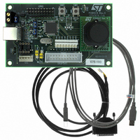
KIT EVAL FOR STV0676 DSP
Manufacturer
STMicroelectronics
Datasheet
1.STV-676-E01.pdf
(22 pages)
Specifications of STV-676-E01
Sensor Type
CMOS Imaging, Color (RGB)
Sensing Range
VGA
Interface
I²C, Digiport
Sensitivity
30 fps
Embedded
Yes, MCU, 8-Bit
Utilized Ic / Part
STV0676, VV6411, VV6501
Lead Free Status / RoHS Status
Contains lead / RoHS non-compliant
Voltage - Supply
-
Lead Free Status / Rohs Status
Lead free / RoHS Compliant
Other names
497-3888
STV-676-E01
STV-676-E01
Available stocks
Company
Part Number
Manufacturer
Quantity
Price


External interfaces
2
2.1
8/22
External interfaces
USB interface
The USB interface is designed to be compliant with version 1.1 of the USB specification.
The STV0676 is a low power device and is therefore suitable for connection to any USB port
on a PC, self-powered hub or when connected to a bus-powered hub.
The device complies with the device framework specified in Chapter 9 of the USB
specification as follows:
●
●
●
●
●
●
●
●
●
●
Table 1.
The best and most consistent performance in terms of image quality is always obtained in
the highest bandwidth setting (alternate 7). Under some circumstances it may not be
possible for the host to allocate this amount of USB bandwidth to the device.
The isochronous settings reserve varying quantities of bandwidth - from 10% to 85% of USB
bandwidth. The lower settings result in poor image quality due to heavy compression
applied to maintain a high framerate streaming of image data, but at the same time leaving
more bandwidth free for other USB devices. This is desirable if more than one camera is to
be used, or if there are other isochronous peripherals connected. The device driver allows
the user to specify the maximum bandwidth they wish to allocate to transfer data from the
device. If the maximum specified by the user is not available, perhaps because another
isochronous device has already reserved that bandwidth, then lower alternates are tried
until one succeeds.
0
1
2
3
4
5
6
7
Alternate setting
The device supports a single high power configuration ( Configuration 1 ).
Endpoint 0 is the default control endpoint and is always supported.
Endpoint 0 supports all of the USB commands required by the device framework.
Vendor specific commands on Endpoint 0 are used for all device control.
Configuration 1 supports a single interface (interface 0).
Interface 0 supports 8 alternate settings (alternates 0-7).
The alternate settings support between 0 and 2 additional endpoints.
Endpoint 1 is used for isochronous transfer of image data.
Endpoint 3 is used for transferring status information, e.g. state of a hardware button.
The endpoints are configured as follows (
Endpoint alternate settings
Not present
Not present
128 bytes / packet; 1 packet / frame
384 bytes / packet; 1 packet / frame
640 bytes / packet; 1 packet / frame
768 bytes / packet; 1 packet / frame
896 bytes / packet; 1 packet / frame
1023 bytes / packet; 1 packet / frame
Endpoint1 (isochronous)
Table 1
) in the alternate settings:
Not present
8 bytes / packet; 1 packet /8 frames
8 bytes / packet; 1 packet /8 frames
8 bytes / packet; 1 packet /8 frames
8 bytes / packet; 1 packet /8 frames
8 bytes / packet; 1 packet /8 frames
8 bytes / packet; 1 packet /8 frames
8 bytes / packet; 1 packet /8 frames
Endpoint3 (interrupt)
STV0676
Related parts for STV-676-E01
Image
Part Number
Description
Manufacturer
Datasheet
Request
R

Part Number:
Description:
KIT REF DESIGN WEB CAM W/676&502
Manufacturer:
STMicroelectronics
Part Number:
Description:
KIT REF DESIGN STV0676/VV6501
Manufacturer:
STMicroelectronics
Datasheet:
Part Number:
Description:
MCU, MPU & DSP Development Tools DISC-BY-STM-02/05
Manufacturer:
STMicroelectronics
Part Number:
Description:
DAUGHTERCARD VV5501 STV0674/676
Manufacturer:
STMicroelectronics
Part Number:
Description:
DAUGHTERCARD VV6501 STV0674/676
Manufacturer:
STMicroelectronics

Part Number:
Description:
none
Manufacturer:
Power-One
Datasheet:
Part Number:
Description:
IC DAUGHTER CARD W/VC5700C&LENS
Manufacturer:
STMicroelectronics
Part Number:
Description:
KIT EVAL DGT CAMERA W/684&VC6700
Manufacturer:
STMicroelectronics

Part Number:
Description:
Suppressor
Manufacturer:
SOLA HEVI DUTY
Datasheet:
Part Number:
Description:
Suppressor
Manufacturer:
SOLA HEVI DUTY
Datasheet:

Part Number:
Description:
1.8V optical mouse sensor
Manufacturer:
STMICROELECTRONICS [STMicroelectronics]
Datasheet:
Part Number:
Description:
Ultra-low power laser motion sensor for laser mouse applications
Manufacturer:
STMICROELECTRONICS [STMicroelectronics]
Datasheet:
Part Number:
Description:
Mono and Colour Digital Video CMOS Image Sensors
Manufacturer:
STMICROELECTRONICS [STMicroelectronics]
Datasheet:
Part Number:
Description:
DUAL-MODE DIGITAL CAMERA CO-PROCESSOR
Manufacturer:
STMICROELECTRONICS [STMicroelectronics]
Datasheet:
Part Number:
Description:
VGA Color CMOS Image Sensor Module
Manufacturer:
STMICROELECTRONICS [STMicroelectronics]
Datasheet: