DK-35TS-LPC2478 Future Designs Inc, DK-35TS-LPC2478 Datasheet - Page 40
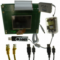
DK-35TS-LPC2478
Manufacturer Part Number
DK-35TS-LPC2478
Description
PROGRAMMERS, DEVELOPMENT SYSTEMS
Manufacturer
Future Designs Inc
Specifications of DK-35TS-LPC2478
Sensor Type
Touch Screen
Interface
I²C
Voltage - Supply
5V
Embedded
Yes, MCU, 16/32-Bit
Utilized Ic / Part
LPC2478 ARM7
For Use With
568-4742 - MODULE DIMM LPC2478 ARM7
Lead Free Status / RoHS Status
Lead free / RoHS Compliant
Sensitivity
-
Sensing Range
-
Other names
622-1034
ARM-35TS-LPC2478
ARM-35TS-LPC2478


NXP Semiconductors
LPC2478
Product data sheet
7.20.1 Features
7.20 I
7.21 I
The LPC2478 contains three I
The I
(SCL), and a serial data line (SDA). Each device is recognized by a unique address and
can operate as either a receiver-only device (e.g., an LCD driver) or a transmitter with the
capability to both receive and send information (such as memory). Transmitters and/or
receivers can operate in either master or slave mode, depending on whether the chip has
to initiate a data transfer or is only addressed. The I
be controlled by more than one bus master connected to it.
The I
The I
The I
and one word select signal. The basic I
master, and one slave. The I
and receive channel, each of which can operate as either a master or a slave.
2
2
•
•
•
•
•
•
•
•
•
•
•
•
•
•
C-bus serial I/O controller
S-bus serial I/O controllers
Conforms to Multimedia Card Specification v2.11.
Conforms to Secure Digital Memory Card Physical Layer Specification, v0.96.
Can be used as a multimedia card bus or a secure digital memory card bus host. The
SD/MMC can be connected to several multimedia cards or a single secure digital
memory card.
DMA supported through the GPDMA controller.
I
I
devices connected to the same bus lines.
Easy to configure as master, slave, or master/slave.
Programmable clocks allow versatile rate control.
Bidirectional data transfer between masters and slaves.
Multi-master bus (no central master).
Arbitration between simultaneously transmitting masters without corruption of serial
data on the bus.
Serial clock synchronization allows devices with different bit rates to communicate via
one serial bus.
Serial clock synchronization can be used as a handshake mechanism to suspend and
resume serial transfer.
The I
2
2
2
2
2
2
C0 is a standard I
C1 and I
C-bus is bidirectional, for inter-IC control using only two wires: a serial clock line
C-bus implemented in LPC2478 supports bit rates up to 400 kbit/s (Fast I
S-bus provides a standard communication interface for digital audio applications.
S-bus specification defines a 3-wire serial bus using one data line, one clock line,
2
C-bus can be used for test and diagnostic purposes.
2
C2 use standard I/O pins and do not support powering off of individual
All information provided in this document is subject to legal disclaimers.
Rev. 2 — 29 September 2010
2
C compliant bus interface with open-drain pins.
2
S interface on the LPC2478 provides a separate transmit
2
C-bus controllers.
2
S connection has one master, which is always the
Single-chip 16-bit/32-bit microcontroller
2
C-bus is a multi-master bus and can
LPC2478
© NXP B.V. 2010. All rights reserved.
2
C-bus).
40 of 91
Related parts for DK-35TS-LPC2478
Image
Part Number
Description
Manufacturer
Datasheet
Request
R

Part Number:
Description:
SOCKET ADAPTER BOARD
Manufacturer:
Future Designs Inc
Datasheet:

Part Number:
Description:
BOARD SCKT ADAPTER FOR TFBGA100
Manufacturer:
Future Designs Inc

Part Number:
Description:
BOARD SCKT ADAPTER FOR TFBGA180
Manufacturer:
Future Designs Inc

Part Number:
Description:
BOARD SCKT ADAPTER FOR TFBGA208
Manufacturer:
Future Designs Inc


Part Number:
Description:
BOARD DEMO FOR PHILIPS PCA9633
Manufacturer:
Future Designs Inc
Datasheet:

Part Number:
Description:
KIT LCD TOUCH 5.7" FOR LPC2478
Manufacturer:
Future Designs Inc

Part Number:
Description:
KIT LCD TOUCH 5.7" FOR LPC3250
Manufacturer:
Future Designs Inc

Part Number:
Description:
BOARD FOR LPC2103 48-LQFP
Manufacturer:
Future Designs Inc


Part Number:
Description:
KIT DEV IND REF DESIGN LPC1768
Manufacturer:
Future Designs Inc

Part Number:
Description:
BOARD FOR LPC9103 10-HVSON
Manufacturer:
Future Designs Inc
