ZEPIR000101ZCOG Zilog, ZEPIR000101ZCOG Datasheet

BOARD COMPUTER SGL EPIR ZDOT

ZEPIR000101ZCOG

Manufacturer Part Number
ZEPIR000101ZCOG
Description
BOARD COMPUTER SGL EPIR ZDOT
Manufacturer
Zilog
Series
Zdots® SBCr
Datasheets

Specifications of ZEPIR000101ZCOG

Sensor Type
Motion, PIR (Pyroelectric Infrared)
Sensing Range
5m x 5m, 60 Degree Detection Pattern
Interface
UART or Hardware
Sensitivity
Adjustable
Voltage - Supply
2.7 V ~ 3.6 V
Embedded
Yes, MCU, 8-Bit
Utilized Ic / Part
ZEPIR0AAS01SBCG
Lead Free Status / RoHS Status
Contains lead / RoHS non-compliant
Other names
269-4711
Introduction
This quick start guide describes how to set up and use Zilog’s ZMOTION Detection Mod-
ule Development Kit. The Kit can be used to demonstrate and evaluate the operation of the
ZMOTION Detection Module in both Hardware and Serial modes.
This quick start guide also provides the steps required for using Hardware mode. For addi-
tional information please refer to the
Manual
Kit Contents
All hardware (except an external adjustable power supply), software and documentation
required to develop your motion detection application is included within the ZMOTION
Detection Module Development Kit.
Hardware
The ZMOTION Detection Module Development Kit includes the following hardware:
Documentation
The related technical documentation (on CD-ROM) includes:
Please refer to the Zilog website at
mentation.
ZMOTION Detection Module Base Board
ZMOTION Detection Module
RS-232 Serial Cable DB9-DB9
5 V DC Universal Power Supply
ZMOTION Detection Module Development Kit User Manual (UM0223)
ZMOTION Detection Module Product Specification (PS0284)
ZMOTION Detection Module Product Brief (PB0223)
(UM0223).
ZMOTION
Development Kit
Quick Start Guide
Copyright ©2011 Zilog
www.zilog.com
ZMOTION Detection Module Development Kit User
www.zilog.com
®
, Inc. All rights reserved.
Detection Module
to obtain the most up-to-date docu-
QS007308-1210

Related parts for ZEPIR000101ZCOG

ZEPIR000101ZCOG Summary of contents

Page 1

... Development Kit Quick Start Guide Introduction This quick start guide describes how to set up and use Zilog’s ZMOTION Detection Mod- ule Development Kit. The Kit can be used to demonstrate and evaluate the operation of the ZMOTION Detection Module in both Hardware and Serial modes. ...

Page 2

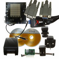
Figure 1. ZMOTION Detection Module Evaluation Kit Components Setting up for Initial Operation The simplest mode in which to use the module is Hardware Mode. In this mode, the sensi- tivity, ambient light level and LED “On” time are all ...

Page 3

Step 1: Unpack the Hardware Remove the ZMOTION Base Board, ZMOTION Module and Power Supply from their protective bags. ESD precautions must be used when handling the ZMOTION Base Board and the ZMOTION Module. Step 2: Attach the ZMOTION Detection ...

Page 4

Step 3: Install the AC Plug Adapter The universal power supply kit features four different plug adapters in one box and the power supply by itself in another. The power supply ships with a slide-out plate that must be removed ...

Page 5

Step 6: Demonstrate the ZMOTION Detection Module After no more than about 30 seconds, generate motion in front of the ZMOTION Detec- tion Module and observe the blue LED D1, which should flash for about 2 seconds. • Adjust R3 ...

Page 6

... NOLOGY DESCRIBED HEREIN OR OTHERWISE. The information contained within this document has been verified according to the general principles of electrical and mechanical engineering. ZMOTION is a trademark or registered trademark of Zilog, Inc. All other product or ser- vice names are the property of their respective owners. QS007308-1210 ZMOTION™ ...

Related keywords