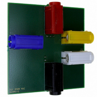
LMP8601MAEVAL/NOPB National Semiconductor, LMP8601MAEVAL/NOPB Datasheet - Page 13

LMP8601MAEVAL/NOPB
Manufacturer Part Number
LMP8601MAEVAL/NOPB
Description
BOARD EVALUATION FOR LMP8601MA
Manufacturer
National Semiconductor
Series
LMP®r
Specifications of LMP8601MAEVAL/NOPB
Channels Per Ic
1 - Single
Amplifier Type
Current Sense
Output Type
Single-Ended
Slew Rate
0.83 V/µs
Current - Output / Channel
48mA
Operating Temperature
-40°C ~ 125°C
Current - Supply (main Ic)
1.1mA
Voltage - Supply, Single/dual (±)
3 V ~ 5.5 V
Board Type
Fully Populated
Utilized Ic / Part
LMP8601
Silicon Manufacturer
National
Silicon Core Number
LMP8601, LMP8601Q
Kit Application Type
Amplifier
Application Sub Type
Current-Sense Amplifier
Kit Contents
Board, Doc
Lead Free Status / RoHS Status
Lead free / RoHS Compliant
-3db Bandwidth
-
Other names
LMP8601MAEVAL
ADDITIONAL SECOND ORDER LOW PASS FILTER
The LMP8601/LMP8601Q has a third order Butterworth low-
pass characteristic with a typical bandwidth of 60 kHz inte-
grated in the preamplifier stage of the part. The bandwidth of
the output buffer can be reduced by adding a capacitor on the
A1 pin to create a first order low pass filter with a time constant
determined by the 100 kΩ internal resistor and the external
filter capacitor.
It is also possible to create an additional second order Sallen-
Key low pass filter by adding external components R
C
in
characteristic.
When the corner frequency of the additional filter is much
lower than 60 kHz, the transfer function of the described am-
plifier van be written as:
Where K
the buffer amplifier.
The above equation can be written in the normalized frequen-
cy response for a 2
The cutt-off frequency ω
cut-off frequency in Hz) is given by:
2
Figure
. Together with the internal 100 kΩ resistor R
1
2, this circuit creates a second order low-pass filter
equals the gain of the preamplifier and K
nd
order low pass filter:
o
in rad/sec (divide by 2
1
as illustrated
π
to get the
2
, C
2
that of
1
and
13
and the quality factor of the filter is given by:
With K
With this filter gain K2= 2x, the design procedure can be very
simple if the two capacitors are chosen to be equal, C
In this case, given the predetermined value of R1 = 100kΩ
( the internal resistor), the quality factor is set solely by the
value of the resistor R
R
first step of the design procedure with the following equation:
For instance, the value of Q can be set to 0.5
Butterworth response, to 1/
or a 0.5 to create a critically damped response. Once the
value of R
design procedure is to calculate the required value of C to give
the desired low-pass cut-off frequency using:
Note that the frequency response achieved using this proce-
dure will only be accurate if the cut-off frequency of the second
order filter is much smaller than the intrinsic 60 kHz low-pass
filter. In other words, to have the frequency response of the
LMP8601/LMP8601Q circuit chosen such that the internal
poles do not affect the external second order filter.
2
can be calculated based on the desired value of Q as the
2
= 2x, the above equation transforms results in:
2
has been found, the second and last step of the
2
.
√
3 to create a Bessel response,
√
2 to create a
www.national.com
1
=C
2
=C.


