INTRODUCTION
linear power amplifiers circuits using the PA50/PA52 pin out.
With ample breadboarding areas it is flexible enough to analyze
a multitude of standard or proprietary circuit configurations.
Critical connections for power supply bypassing are pre-wired.
Components not usually readily available in engineering labs
are provided. External connection to the evaluation kit can be
made via the terminal block and terminal pads at the edges of
the circuit board. The terminal pads are suitable for soldering
standard banana jacks or direct soldering of wires. The schematic
is shown in Figure 2.
BEFORE YOU GET STARTED
* All Apex Precision Power amplifiers should be handled using
* Do not change connections while the circuit is powered.
* Initially set all power supplies to the minimum operating volt-
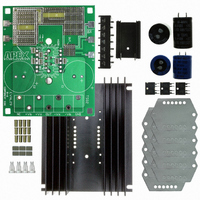
PARTS LIST
Apex Part #
HS18
MS04
EVAL29
60SPG00001
OX7R105KWN
TS02
TWO5
EC05
EC03
EK27U
This easy-to-use kit provides a platform for the evaluation of
proper ESD precautions.
age allowed in the device data sheet.
Evaluation Kit for PA50, PA52 Power Op Amps
http://www.cirrus.com
EK27 PA50, PA52
Description
Heatsink
PC mount Cage Jacks
PC Board
Spacer Grommets
1µF Cap 1825B105K201N,
Novacap
Terminal Strip
Beau Interconnect 66507
Thermal Washer
2200 µf Cap 100V
United Chemi-Con
82DA222M100KC2D
680µF 200V
United Chemi-Con
KMH200VN681M25X40T2
P r o d u c t I n n o v a t i o n F r o m
P r o d u c t I n n o v a t i o n F r o m
1 Bag/12 each
1 Box/12 each
Quantity
Copyright © Cirrus Logic, Inc. 2009
1
1
4
6
1
2
2
(All Rights Reserved)
ASSEMBLY
During assembly refer to Figure 1
1.
2. Solder the surface mount ceramic capacitors to the com-
3. Mount the electrolytic capacitors at C1 and C2 from the
4. Mount the terminal strip TS02 to the component side of the
5. Use #14 sleeving to insulate and align at least 2 opposite
6. Add other components to complete your circuit design. Note
7.
8. Apply TW05 thermal washer to the bottom of the PA50.
9. Place the assembled circuit board over the pins of the
10. Mount the circuit board assembly to the heat sink with #6
11. Tighten the screws that mount the amplifier to the heat sink
Note that each circuit board side is identified. From the
circuit side of the circuit board (not the component side)
insert and solder cage jack MS04 at pins 1-12. Be sure
that the cage jack sits flush with the surface of the circuit
board.
ponent of the circuit board at C3-C7.
component side of the circuit board and solder from the
circuit side of the circuit board. Note polarity and be sure
to fill the holes with solder. Use correct voltage capacitor
for your application.
circuit board. Make sure the terminal strip sits flat against
the circuit board and be sure to fill the holes with solder.
pins of the amplifier.
that the solder terminals labeled 2 and 3 are left for you to
connect to the amplifier via the components that you will
add for your particular design.
Push the four nylon spacers into the circuit board from
the circuit side of the circuit board at the four corner loca-
tions.
Mount the amplifier to the HS18 heat sink provided and
loosely attach with #6 screw and nut.
amplifier making sure that the pin 1 location on the circuit
board matches up with pin 1 of the amplifier. Insert the pins
of the amplifier into the circuit board mating cage jacks.
self tapping or sheet metal screws at the four corners of
the heat sink.
via the access holes in the circuit board.
APEX − EK27UREVC
EK27
MAY 2009
EK27
1