EK61 Cirrus Logic Inc, EK61 Datasheet - Page 9
EK61
Manufacturer Part Number
EK61
Description
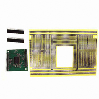
KIT EVALUATION PA78/PA79
Manufacturer
Cirrus Logic Inc
Series
Apex Precision Power™r
Specifications of EK61
Channels Per Ic
1 - Single, 2 - Dual
Amplifier Type
Power
Output Type
Single-Ended
Board Type
Bare (Unpopulated)
Utilized Ic / Part
PA78DK, PA79DK
Product
Amplifier Modules
Description/function
Audio Amplifiers
For Use With/related Products
PA78DK, PA79DK
Lead Free Status / RoHS Status
Contains lead / RoHS non-compliant
Operating Temperature
-
Current - Output / Channel
-
Voltage - Supply, Single/dual (±)
-
-3db Bandwidth
-
Slew Rate
-
Current - Supply (main Ic)
-
Lead Free Status / RoHS Status
Lead free / RoHS Compliant, Contains lead / RoHS non-compliant
Other names
598-1398
EK61
EK61


standby. An increase in the idle current in the output stage of the amplifier will improve phase margin for small sig-
nals although will increase the overall supply current.
Current can be injected into the output stage by adding a resistor, R
will depend upon the application but 500µA (50V V+ supply/100K) of added bias current shows significant improve-
ment in the small signal phase plots. Adding this resistor has little to no impact on small signal gain or large signal
performance as under these conditions the current in the input stage is elevated over its idle value. It should also
be noted that connecting a resistor to the upper supply only injects a fixed current and if the upper supply is fixed
and well bypassed. If the application includes variable or adjustable supplies, a current source diode could also be
used. These two terminal components combine a JFET and resistor connected within the package to behave like
a current source.
As a second stability measure, the PA78 is externally compensated and performance can be optimized to the ap-
plication. Unlike the R
the large signal response of the amplifier. Refer to the small and large signal response plots as a guide in making
the tradeoffs between bandwidth and stability. Due to the unique design of the PA78, two symmetric compensation
networks are required. The compensation capacitor Cc must be rated for a working voltage of the full operating
supply voltage (+V
temperature.
The PA78 requires an external 33pF capacitor between C
output. This capacitor should be rated for the full supply voltage (+V
LARGE SIGNAL PERFORMANCE
As the amplitude of the input signal increases, the internal dynamic current sources increase the operation band-
width of the amplifier. This unique performance is apparent in its slew rate, pulse response, and large signal perfor-
mance plots. Recall the previous discussion about the relationships between signal amplitude, supply current, and
slew rate. As the amplitude of the input amplitude increases from 1V
µs to well over 350V/µs.
Notice the knee in the Rise and Fall times plot, at approximately 6V
becomes clipped by the supply rails and the amplifier is no longer operating in a closed loop fashion. The rise and
fall times become faster as the dynamic current sources are providing maximum current for slewing. The result of
this amplifier architecture is that it slews fast, but allows good control of overshoot for large input signals. This can
be seen clearly in the large signal Transient Response plots.
hEATSINKING AND SAFE OPERATING AREA
The MOSFET output stage of the PA78 is not limited by second breakdown considerations as in bipolar output
stages. Only thermal considerations of the package and current handling capabilities limit the Safe Operating Area.
The SOA plots include power dissipation limitations which are dependent upon case temperature. Keep in mind
that the dynamic current sources which drive high slew rates can increase the operating temperature of the ampli-
fier during periods of repeated slewing. The plot of supply current vs. input signal amplitude for a 100 kHz signal
provides an indication of the supply current with repeated slewing conditions. This application dependent condition
must be considered carefully.
The output stage is self-protected against transient flyback by the parasitic body diodes of the output stage. How-
ever, for protection against sustained high energy flyback, external, fast recovery diodes must be used.
CURRENT LIMIT
tions diagram. For maximum reliability and protection, the largest resistor value should be used. The minimum
practical value for R
the optimum value for R
with supply voltages over 200V.
PA78U
For proper operation, the current limit resistor, R
S
P r o d u c t I n n o v a t i o n F r o m
LIM
to –V
BIAS
is about 12Ω. However, refer to the SOA curves for each package type to assist in selecting
LIM
S
technique, external phase compensation maintains the low idle current but does affect
). NPO capacitors are recommended to maintain the desired level of compensation over
in the intended application. Current limit may not protect against short circuit conditions
LIM
C
- and –V
, must be connected as shown in the external connec-
S
S
P-P
to prevent oscillations in the falling edge of the
P-P
BIAS
to –V
to 15V
input voltage. Beyond this point the output
, between C
S
).
P-P
, the slew rate increases from 50V/
C
- and V
S
+. The size of R
PA78
BIAS
9
Related parts for EK61
Image
Part Number
Description
Manufacturer
Datasheet
Request
R

Part Number:
Description:
Development Kit
Manufacturer:
Cirrus Logic Inc
Datasheet:
Part Number:
Description:
Development Kit
Manufacturer:
Cirrus Logic Inc
Datasheet:


Part Number:
Description:
High-efficiency PFC + Fluorescent Lamp Driver Reference Design
Manufacturer:
Cirrus Logic Inc
Datasheet:
Part Number:
Description:
Development Kit
Manufacturer:
Cirrus Logic Inc
Datasheet:
Part Number:
Description:
Development Kit
Manufacturer:
Cirrus Logic Inc
Datasheet:

Part Number:
Description:
Development Kit
Manufacturer:
Cirrus Logic Inc
Datasheet:
Part Number:
Description:
Development Kit
Manufacturer:
Cirrus Logic Inc
Datasheet:
Part Number:
Description:
Development Kit
Manufacturer:
Cirrus Logic Inc
Datasheet:
Part Number:
Description:
Development Kit
Manufacturer:
Cirrus Logic Inc
Datasheet:

Part Number:
Description:
EVALUATION BOARD FOR CS8427
Manufacturer:
Cirrus Logic Inc
Datasheet:

Part Number:
Description:
BOARD EVAL FOR CS8416 RCVR
Manufacturer:
Cirrus Logic Inc
Datasheet:

Part Number:
Description:
EVALUATION BOARD FOR CS8420
Manufacturer:
Cirrus Logic Inc
Datasheet:

Part Number:
Description:
KIT DEVELOPMENT EP9315 ARM9
Manufacturer:
Cirrus Logic Inc
Datasheet:

Part Number:
Description:
KIT DEVELOPMENT EP9302 ARM9
Manufacturer:
Cirrus Logic Inc
Datasheet: