NCP690MNADT2GEVB ON Semiconductor, NCP690MNADT2GEVB Datasheet
NCP690MNADT2GEVB
Manufacturer Part Number
NCP690MNADT2GEVB
Description
EVAL BOARD FOR NCP690MNADT2G
Manufacturer
ON Semiconductor
Specifications of NCP690MNADT2GEVB
Design Resources
NCP690MNADT2GEVB BOM NCP690MNADT2GEVB Gerber Files NCP690 Demo Brd Schematic
Channels Per Ic
1 - Single
Voltage - Output
1.25 ~ 5 V
Current - Output
1A
Regulator Type
Positive Adjustable
Board Type
Fully Populated
Utilized Ic / Part
NCP690
Lead Free Status / RoHS Status
Lead free / RoHS Compliant
Voltage - Input
-
Operating Temperature
-
Lead Free Status / Rohs Status
Lead free / RoHS Compliant
For Use With/related Products
NCP690MNADT2G
Other names
NCP690MNADT2GEVBOS


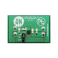
Test Procedure for the NCP690, 1A, Adjustable LDO
Test Setup:
Please solder feedback resistors to program the output
voltage. The resistors should be 1206 SMD type.
*During the tests please leave the JP1 disconnected
Figure 1
06-MAY-09
Page 1 of 3
www.onsemi.com
Related parts for NCP690MNADT2GEVB
Image
Part Number
Description
Manufacturer
Datasheet
Request
R

Part Number:
Description:
ON Semiconductor [VOLTAGE REGULATOR]
Manufacturer:
ON Semiconductor
Datasheet:
Part Number:
Description:
357-036-542-201 CARDEDGE 36POS DL .156 BLK LOPRO
Manufacturer:
ON Semiconductor
Datasheet:
Part Number:
Description:
357-036-542-201 CARDEDGE 36POS DL .156 BLK LOPRO
Manufacturer:
ON Semiconductor
Datasheet:
Part Number:
Description:
357-036-542-201 CARDEDGE 36POS DL .156 BLK LOPRO
Manufacturer:
ON Semiconductor
Datasheet:
Part Number:
Description:
357-036-542-201 CARDEDGE 36POS DL .156 BLK LOPRO
Manufacturer:
ON Semiconductor
Datasheet:
Part Number:
Description:
357-036-542-201 CARDEDGE 36POS DL .156 BLK LOPRO
Manufacturer:
ON Semiconductor
Datasheet:
Part Number:
Description:
357-036-542-201 CARDEDGE 36POS DL .156 BLK LOPRO
Manufacturer:
ON Semiconductor
Datasheet:
Part Number:
Description:
357-036-542-201 CARDEDGE 36POS DL .156 BLK LOPRO
Manufacturer:
ON Semiconductor
Datasheet:
Part Number:
Description:
357-036-542-201 CARDEDGE 36POS DL .156 BLK LOPRO
Manufacturer:
ON Semiconductor
Datasheet:
Part Number:
Description:
357-036-542-201 CARDEDGE 36POS DL .156 BLK LOPRO
Manufacturer:
ON Semiconductor
Datasheet:
Part Number:
Description:
357-036-542-201 CARDEDGE 36POS DL .156 BLK LOPRO
Manufacturer:
ON Semiconductor
Datasheet:
Part Number:
Description:
Manufacturer:
ON Semiconductor
Datasheet:
Part Number:
Description:
Manufacturer:
ON Semiconductor
Datasheet:
Part Number:
Description:
Manufacturer:
ON Semiconductor
Datasheet:
NCP690MNADT2GEVB Summary of contents
Page 1
Test Procedure for the NCP690, 1A, Adjustable LDO Test Setup: 06-MAY-09 Please solder feedback resistors to program the output voltage. The resistors should be 1206 SMD type. *During the tests please leave the JP1 disconnected Figure 1 Page 1 of ...
Page 2
Test Procedure for the NCP690, 1A, Adjustable LDO Required Equipment Voltmeters 2 x Ampere meters DC Power Supply – 6V, 1A Electronic Load Required Components: R1 Feedback Resistors required to set the Output Voltage. Test Procedure: ...
Page 3
Test Procedure for the NCP690, 1A, Adjustable LDO Please also note that the feedback resistors should be chosen to satisfy the minimum output current requirement, which is 100µA. 1. Connect the test setup as shown on Figure 1, 2. Set ...