NCP690MN50T2GEVB ON Semiconductor, NCP690MN50T2GEVB Datasheet - Page 12
NCP690MN50T2GEVB
Manufacturer Part Number
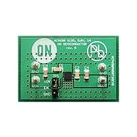
NCP690MN50T2GEVB
Description
EVAL BOARD FOR NCP690MN50T2G
Manufacturer
ON Semiconductor
Specifications of NCP690MN50T2GEVB
Design Resources
NCP690MN50T2GEVB BOM NCP690MN50T2GEVB Gerber Files NCP690MN50T2GEVB Schematic
Channels Per Ic
1 - Single
Voltage - Output
5V
Current - Output
1A
Regulator Type
Positive Fixed
Board Type
Fully Populated
Utilized Ic / Part
NCP690
Lead Free Status / RoHS Status
Lead free / RoHS Compliant
Voltage - Input
-
Operating Temperature
-
Lead Free Status / Rohs Status
Lead free / RoHS Compliant
For Use With/related Products
NCP690MN50T2G
Other names
NCP690MN50T2GEVBOS


divider network as shown on Figure 4. The output voltage
and resistors should be chosen using Equations 1 and 2.
Choose R
current and to minimize noise contribution to the output
voltage. Use Equation 2 to find the required value for R
Thermal Characteristics
become necessary to provide some thermal relief. The
maximum power dissipation supported by the device is
dependent upon board design and layout. Mounting pad
configuration on the PCB, the board material, and the
ambient temperature affect the rate of junction temperature
rise for the part. When the NCP690 has good thermal
conductivity through the PCB, the junction temperature will
be relatively low with high power applications. The
maximum dissipation the NCP690 can handle is given by:
then the NCP690 can dissipate up to 1 W when the ambient
temperature (T
Input bias current I
As power dissipated in the NCP690 increases, it might
Since T
V
R
OUT
2
J
1
^ R
is not recommended to exceed 125°C (T
arbitrarily to minimize errors due to the bias
+ 1.250 1 )
A
1
) is 25°C.
P
V
1.25
D(MAX)
OUT
1
* 1
ADJ
+
is typically less than 210 nA.
[T
R
R
1
2
J(MAX)
) (I
R
qJA
* T
ADJ
A
@ R
]
1
)
J(MAX)
(eq. 1)
(eq. 2)
(eq. 3)
http://onsemi.com
2
.
),
12
from the following equations:
or
Hints
wide as possible. When the impedance of these traces is
high, there is a chance to pick up noise or cause the regulator
to malfunction. Place external components, especially the
output capacitor, as close as possible to the NCP690, and
make traces as short as possible.
The power dissipated by the NCP690 can be calculated
V
250
200
150
100
50
Figure 32. Thermal Resistance vs. Copper Area
IN
0
P
0
and GND printed circuit board traces should be as
D
[ V
V
IN(MAX)
IN
FR4 − 1.0 oz
FR4 − 2.0 oz
(I
GND
200
COPPER AREA (mm
[
@I
P
OUT
D(MAX)
) ) I
I
OUT
) (V
400
OUT
) I
OUT
(V
GND
2
IN
)
* V
I
OUT
600
OUT
)
)
(eq. 4)
(eq. 5)
800
Related parts for NCP690MN50T2GEVB
Image
Part Number
Description
Manufacturer
Datasheet
Request
R

Part Number:
Description:
ON Semiconductor [VOLTAGE REGULATOR]
Manufacturer:
ON Semiconductor
Datasheet:
Part Number:
Description:
357-036-542-201 CARDEDGE 36POS DL .156 BLK LOPRO
Manufacturer:
ON Semiconductor
Datasheet:
Part Number:
Description:
357-036-542-201 CARDEDGE 36POS DL .156 BLK LOPRO
Manufacturer:
ON Semiconductor
Datasheet:
Part Number:
Description:
357-036-542-201 CARDEDGE 36POS DL .156 BLK LOPRO
Manufacturer:
ON Semiconductor
Datasheet:
Part Number:
Description:
357-036-542-201 CARDEDGE 36POS DL .156 BLK LOPRO
Manufacturer:
ON Semiconductor
Datasheet:
Part Number:
Description:
357-036-542-201 CARDEDGE 36POS DL .156 BLK LOPRO
Manufacturer:
ON Semiconductor
Datasheet:
Part Number:
Description:
357-036-542-201 CARDEDGE 36POS DL .156 BLK LOPRO
Manufacturer:
ON Semiconductor
Datasheet:
Part Number:
Description:
357-036-542-201 CARDEDGE 36POS DL .156 BLK LOPRO
Manufacturer:
ON Semiconductor
Datasheet:
Part Number:
Description:
357-036-542-201 CARDEDGE 36POS DL .156 BLK LOPRO
Manufacturer:
ON Semiconductor
Datasheet:
Part Number:
Description:
357-036-542-201 CARDEDGE 36POS DL .156 BLK LOPRO
Manufacturer:
ON Semiconductor
Datasheet:
Part Number:
Description:
357-036-542-201 CARDEDGE 36POS DL .156 BLK LOPRO
Manufacturer:
ON Semiconductor
Datasheet:
Part Number:
Description:
Manufacturer:
ON Semiconductor
Datasheet:
Part Number:
Description:
Manufacturer:
ON Semiconductor
Datasheet:
Part Number:
Description:
Manufacturer:
ON Semiconductor
Datasheet: