LP38512TS-1.8EV National Semiconductor, LP38512TS-1.8EV Datasheet

BOARD EVAL FOR LP38512TS-1.8

LP38512TS-1.8EV

Manufacturer Part Number
LP38512TS-1.8EV
Description
BOARD EVAL FOR LP38512TS-1.8
Manufacturer
National Semiconductor
Datasheets

Specifications of LP38512TS-1.8EV

Channels Per Ic
1 - Single
Voltage - Output
1.8V
Current - Output
1.5A
Voltage - Input
2.25 ~ 5.5V
Regulator Type
Positive Fixed
Operating Temperature
-40°C ~ 125°C
Board Type
Fully Populated
Utilized Ic / Part
LP38512
Lead Free Status / RoHS Status
Contains lead / RoHS non-compliant
© 2007 National Semiconductor Corporation
LP38512TS-1.8 Evaluation
Board
Introduction
This board is designed to enable the evaluation of the
LP38512TS-1.8 Voltage Regulator. Each board is assembled
and tested in the factory. This evaluation board has the
TO-263 5-lead package mounted.
General Description
The LP38512 is a linear regulator capable of supplying up to
1.5A of output current, and incorporates Enable and Error flag
features.
The device has been designed to work with 10 µF ceramic
input and output capacitors. Footprints areas for C
C
Operation
The input voltage, applied between V
at least 2.25V, and no higher than 5.5V.
Loads can be connected to V
Test points are provided on the board to allow monitoring of
V
If the application does not require the Enable function, the EN
pin should be connected to directly to the adjacent V
Enable Operation
The Enable On threshold is typically 1.2V, and typically has
200mV of hysteresis. The voltage signal should rise and fall
cleanly, and promptly, through these thresholds.
The Enable pin (EN) has no internal pull-up or pull-down to
establish a default condition and, as a result, this pin must be
terminated either actively or passively.
If the Enable pin is driven from a single ended device (such
as the collector of a discrete transistor) a pull-up resistor to
V
proper operation. A 1 kΩ to 100 kΩ resistor can be used as
OUT
IN
OUT
, or a pull-down resistor to ground, will be required for
, V
will allow for a variety of sizes.
IN
, Enable, and ERROR signals during operation
FIGURE 1. V
OUT
OUT
with reference to GND.
vs. V
IN
and GND, should be
EN
300283
30028310
IN
IN
pin.
and
National Semiconductor
Application Note 1676
Don Jones
November 5, 2007
the pull-up or pull-down resistor to establish default condition
for the EN pin. The resistor value selected should be appro-
priate to swamp out any leakage in the external single ended
device, as well as any stray capacitance.
If the Enable pin is driven from a source that actively pulls high
and low (such as a CMOS rail to rail comparator output), the
pull-up, or pull-down, resistor is not required.
If the application does not require the Enable function, the EN
pin should be connected to directly to the adjacent V
The status of the Enable pin also affects the behavior of the
ERROR Flag. While the Enable pin is high the regulator con-
trol loop will be active and the ERROR Flag will report the
status of the output voltage. When the Enable pin is taken low
the regulator control loop is shutdown, the output is turned off,
and the internal logic will immediately force the ERROR Flag
pin low.
ERROR Flag
When the LP38512 Enable pin is high, the ERROR Flag pin
will produce a logic low signal when the output drops by more
than 10% (typical) from the nominal output voltage. The drop
in output voltage may be due to low input voltage, current
limiting, or thermal limiting. This flag has a built in hysteresis.
The output voltage will need to rise to within 5% of the nominal
output voltage for the ERROR Flag to return to a logic high
state. It should also be noted that when the Enable pin is
pulled low, the ERROR Flag pin is forced to be low as well.
The internal ERROR flag comparator has an open drain out-
put stage. Hence, the ERROR pin requires an external pull-
up resistor. The value of the pull-up resistor should be in the
range of 2 kΩ to 100 kΩ, and should be connected to the
LP38512 output voltage pin. The ERROR Flag pin should not
be pulled-up to any voltage source higher than V
flow through an internal parasitic diode may cause unexpect-
ed behavior. When the input voltage is less than typically
1.25V the status of the ERROR flag output will not be reliable.
FIGURE 2. Enable Threshold
www.national.com
30028303
IN
as current
IN
pin.

Related parts for LP38512TS-1.8EV

LP38512TS-1.8EV Summary of contents

Page 1

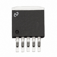
... LP38512TS-1.8 Evaluation Board Introduction This board is designed to enable the evaluation of the LP38512TS-1.8 Voltage Regulator. Each board is assembled and tested in the factory. This evaluation board has the TO-263 5-lead package mounted. General Description The LP38512 is a linear regulator capable of supplying up to 1.5A of output current, and incorporates Enable and Error flag features. The device has been designed to work with 10 µ ...

Page 2

... Although there is only approximately 0.28 square inches of copper area immediately under the tab, the top copper sur- face area is extended to additional copper area on the bottom of the board by nine thermal vias. With the 30°C/W thermal rating the LP38512TS evaluation board will deliver the rated 3A output current if V ≤ 1.8V, and T 25° ...

Page 3

Connection Diagram Schematic Diagram PCB Layout Evaluation Board Schematic Evaluation Board Component and Pin Layout 3 30028304 30028301 30028311 www.national.com ...

Page 4

... Terminal ; Blue Resistor: 10 kΩ ±1%; 0805 Resistor: 10 kΩ ±1%; 0805 Not Installed Turret Terminal : Mounting Hole Diameter = 0.062” 4 Manufacturer Part Number LP38512TS-1.8 NOPB Corporation AVX 1210ZC106KAT2A AXV 1210ZC106KAT2A 108–0901–001 108–0902–001 Johnson Components 108–0903–001 108– ...

Page 5

Notes 5 www.national.com ...

Page 6

... For more National Semiconductor product information and proven design tools, visit the following Web sites at: Products Amplifiers www.national.com/amplifiers Audio www.national.com/audio Clock Conditioners www.national.com/timing Data Converters www.national.com/adc Displays www.national.com/displays Ethernet www.national.com/ethernet Interface www.national.com/interface LVDS www.national.com/lvds Power Management www.national.com/power Switching Regulators www.national.com/switchers LDOs www ...

Related keywords