MCP1726EV Microchip Technology, MCP1726EV Datasheet - Page 15
MCP1726EV
Manufacturer Part Number
MCP1726EV
Description
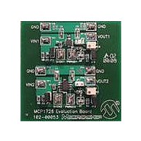
BOARD EVAL FOR MCP1726
Manufacturer
Microchip Technology
Datasheets
1.MCP1726EV.pdf
(2 pages)
2.MCP1726EV.pdf
(30 pages)
3.MCP1726EV.pdf
(24 pages)
4.MCP1726EV.pdf
(4 pages)
5.MCP1726EV.pdf
(24 pages)
Specifications of MCP1726EV
Channels Per Ic
1 - Single
Voltage - Output
0.8 ~ 5V
Current - Output
1A
Voltage - Input
2.3 ~ 6V
Regulator Type
Positive Adjustable
Operating Temperature
-40°C ~ 125°C
Board Type
Fully Populated
Utilized Ic / Part
MCP1726
Processor To Be Evaluated
MCP1726
Silicon Manufacturer
Microchip
Silicon Core Number
MCP1726
Kit Application Type
Power Management - Voltage Regulator
Application Sub Type
LDO
Kit Contents
Board Cables CD Docs
Rohs Compliant
Yes
Lead Free Status / RoHS Status
Contains lead / RoHS non-compliant
Lead Free Status / RoHS Status
Lead free / RoHS Compliant, Contains lead / RoHS non-compliant
Available stocks
Company
Part Number
Manufacturer
Quantity
Price
Company:

Part Number:
MCP1726EV
Manufacturer:
Microchip Technology
Quantity:
135


© 2006 Microchip Technology Inc.
2.5.3
The MCP1726 Evaluation Board has one dual-status LED. The dual LED (D1) contains
a red LED and a green LED. The red portion of the LED illuminates to indicate that input
voltage is present.
The green portion of the LED (D1) is used for power good (PWRGD) indication. During
normal operation, if the LDO output is in regulation, the green portion of D1 is
illuminated to provide indication that power is good. If the output voltage of the LDO
falls below the power good threshold limit (below 92% (typical) of the nominal output
voltage regulation value) for any reason (input voltage too low, overtemperature, output
short circuit), the green portion of the LED will turn off. The green portion of the LED is
driven off of the PWRGD2 output.
The power good output (PWRGD2) can be monitored by connecting to TP5. The power
good output of the MCP1726 device is an open-drain output. On the MCP1726
Evaluation Board, the PWRGD2 output can be pulled up to either the LDO input or
output voltage. This can be accomplished through jumpers JP2 and JP3, respectively.
To pull the PWRGD2 output up to the input voltage of the LDO, populate jumper JP2
(place one of the black shorting tabs on the jumper) and make sure that jumper JP3 is
not populated. To pull the PWRGD2 output up to the output voltage, populate jumper
JP3 and make sure that jumper JP2 is not populated. Upon shipment, the board is
configured to have PWRGD2 pulled up to the input voltage. Because the PWRGD2
output is driving the green portion of the D1 LED, the voltage at the PWRGD2 test point
will be clamped to the forward voltage of the LED. If you want to have the PWRGD2
voltage be pulled all the way up to the input or output voltage, remove the D1 LED.
2.5.4
The MCP1726 device has a power good time delay feature that allows the user to set
the time delay from when the output voltage is in regulation to when the power good
output (PWRGD) goes high. This feature is implemented by the C
device (see data sheet for more details). Circuit 2 of the MCP1726 Evaluation Board is
populated with a 1000 pF capacitor (C3) for the C
typical delay time of 3 ms.
2.5.5
The input and output capacitors (C1 and C2, respectively) for Circuit 2 of the MCP1726
Evaluation Board are populated with 4.7μF, 6.3V ceramic capacitors. The pads for
these devices have been constructed in such a manner that 0805, 1206 and 1210 size
surface-mount capacitors can be used. This allows the user to populate the board with
capacitors of various values and voltage ratings that mimic their application.
2.5.6
As stated earlier, the MCP1726 Evaluation Board is designed to handle either the
adjustable or fixed-output voltage version of the device (board comes populated with
the adjustable output voltage version). When testing a fixed-output voltage version of
the device, jumper JP1 should be populated (use the additional black jumper top that
is provided). This will connect pin 7 of U1 to the VOUT2 output (for the fixed-output
voltage devices, pins 7 and 8 of the MCP1726 are both V
proper operation.
Power Present and Power Good (PWRGD2) Indication
Power Good Time Delay
Input and Output Capacitors
Testing Fixed-Output Voltage Devices
DELAY
pin capacitor. This gives a
OUT
), which is necessary for
DELAY
DS51550B-page 11
pin on the
Related parts for MCP1726EV
Image
Part Number
Description
Manufacturer
Datasheet
Request
R

Part Number:
Description:
Manufacturer:
Microchip Technology Inc.
Datasheet:
Part Number:
Description:
Manufacturer:
Microchip Technology Inc.
Datasheet:
Part Number:
Description:
Manufacturer:
Microchip Technology Inc.
Datasheet:
Part Number:
Description:
Manufacturer:
Microchip Technology Inc.
Datasheet:
Part Number:
Description:
Manufacturer:
Microchip Technology Inc.
Datasheet:
Part Number:
Description:
Manufacturer:
Microchip Technology Inc.
Datasheet:
Part Number:
Description:
Manufacturer:
Microchip Technology Inc.
Datasheet:
Part Number:
Description:
Manufacturer:
Microchip Technology Inc.
Datasheet: