SOT223-3EV-VREG Microchip Technology, SOT223-3EV-VREG Datasheet - Page 12
SOT223-3EV-VREG
Manufacturer Part Number
SOT223-3EV-VREG
Description
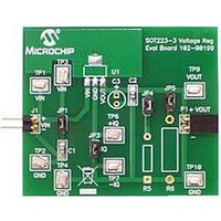
BOARD EVAL SOT223-3 VOLTAGE REG
Manufacturer
Microchip Technology
Datasheet
1.SOT223-3EV-VREG.pdf
(20 pages)
Specifications of SOT223-3EV-VREG
Channels Per Ic
1 - Single
Regulator Type
Positive Fixed
Board Type
Partially Populated
Utilized Ic / Part
SOT-23-3 Package
Silicon Manufacturer
Microchip
Application Sub Type
Voltage Regulator
Kit Application Type
Power Management - Voltage Regulator
Silicon Core Number
MCP1791, MCP1824, MCP1825, MCP1826
Lead Free Status / RoHS Status
Lead free / RoHS Compliant
Current - Output
-
Voltage - Output
-
Voltage - Input
-
Operating Temperature
-
Lead Free Status / Rohs Status
Lead free / RoHS Compliant


SOT223-3 Voltage Regulator Evaluation Board User’s Guide
DS51779A-page 8
10. Add a load selection jumper, JP4 or JP5.
11. Read the Ground Current directly from the ammeter connected to the testpoints
12. The data collected will be the “ground current” versus load current.
2.3.2
R5 and R6 are used to set the desired load values. One choice is to set R5 to the
minimum current wanted for testing. R6 would then be set to a value appropriate for the
specific tests. Either value may be selected by adding their respective jumpers.
2.3.3
Dynamic Line Step response may be evaluated by connecting an electronically
switched input voltage to testpoints TP1(+) and TP2(-) or to connector J1.
An oscilloscope is connected to TP3 (Ch1 Trigger), TP9 (Ch2) and TP10 (Gnd). An
appropriate load is selected using R5 and JP4 or R6 and JP5. The input voltage is then
electronically switched from a low voltage to a higher one. The corresponding voltage
waveform data of the voltage regulator response is captured by the oscilloscope.
Microchip will be offering a Line Step module that connects directly to connector J1.
The Line Step module will be capable of switching between two voltage levels that the
user supplies.
2.3.4
Dynamic Load Step response may be evaluated by connecting an electronically
switched load to testpoints TP9(+) and TP10(-), or to connector P1. An oscilloscope is
connected to the electronic load switch signal (Ch1 Trigger), to TP9 (Ch2) and
TP10(Gnd). The load is then electronically switched from a high resistance to a low
resistance. The corresponding voltage waveform data of the voltage regulator
response is captured by the oscilloscope. Microchip will be offering a Load Step module
that connects directly to connector P1. The Load Step module has several selectable
load values populated on board to cover a wide range of loads. The load has the ability
to be electronically or manually switched.
2.3.5
Power Supply Rejection Ratio tests are performed by removing the input capacitor
jumper, JP1, and connecting an appropriate PSRR analyzer to the SOT223-3 Voltage
Regulator Evaluation Board. The PSRR analyzer may then sweep the input voltage
frequencies and record the corresponding output voltages.
TP6 and TP7.
Load Resistance
Line Step
Load Step
Power Supply Rejection Ratio (PSRR)
© 2008 Microchip Technology Inc.
Related parts for SOT223-3EV-VREG
Image
Part Number
Description
Manufacturer
Datasheet
Request
R

Part Number:
Description:
Manufacturer:
Infineon Technologies
Datasheet:
Part Number:
Description:
Manufacturer:
Infineon Technologies
Datasheet:
Part Number:
Description:
Manufacturer:
Infineon Technologies
Datasheet:
Part Number:
Description:
Manufacturer:
Infineon Technologies
Datasheet:
Part Number:
Description:
Manufacturer:
Infineon Technologies
Datasheet:
Part Number:
Description:
Manufacturer:
Infineon Technologies
Datasheet:
Part Number:
Description:
Manufacturer:
Infineon Technologies
Datasheet:
Part Number:
Description:
Manufacturer:
Infineon Technologies
Datasheet:
Part Number:
Description:
Manufacturer:
Infineon Technologies
Datasheet:
Part Number:
Description:
Manufacturer:
Infineon Technologies
Datasheet:
Part Number:
Description:
Manufacturer:
Infineon Technologies
Datasheet:
Part Number:
Description:
Manufacturer:
Infineon Technologies
Datasheet: