SOT89-3EV-VREG Microchip Technology, SOT89-3EV-VREG Datasheet - Page 9
SOT89-3EV-VREG
Manufacturer Part Number
SOT89-3EV-VREG
Description
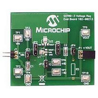
BOARD EVAL SOT89-3 VOLTAGE REG
Manufacturer
Microchip Technology
Datasheets
1.SOT89-3EV-VREG.pdf
(24 pages)
2.SOT89-3EV-VREG.pdf
(26 pages)
3.SOT89-3EV-VREG.pdf
(28 pages)
4.SOT89-3EV-VREG.pdf
(22 pages)
5.SOT89-3EV-VREG.pdf
(22 pages)
Specifications of SOT89-3EV-VREG
Channels Per Ic
1 - Single
Regulator Type
Positive Fixed
Board Type
Partially Populated
Utilized Ic / Part
SOT-89-3 Package
Silicon Manufacturer
Microchip
Application Sub Type
Voltage Regulator
Kit Application Type
Power Management - Voltage Regulator
Silicon Core Number
MCP1700A, MCP1701A, MCP1702, MCP1703
Lead Free Status / RoHS Status
Lead free / RoHS Compliant
Current - Output
-
Voltage - Output
-
Voltage - Input
-
Operating Temperature
-
Lead Free Status / Rohs Status
Lead free / RoHS Compliant


1.1
1.2
© 2009 Microchip Technology Inc.
INTRODUCTION
WHAT IS THE SOT89-3 VOLTAGE REGULATOR EVALUATION BOARD?
The SOT89-3 Voltage Regulator Evaluation Board is designed to provide functional
evaluation of Microchip Voltage Regulators that utilize the SOT89-3 package and the
following device pinouts:
The SOT89-3 Voltage Regulator Evaluation Board does not come with a voltage
regulator soldered onto the board. This allows the user to attach the voltage regulator
of their choosing to the board and perform quiescent current, ground current, PSRR,
and other desired tests.
The SOT89-3 Voltage Regulator Evaluation Board is based upon a modular concept
which will allow the user to plug in additional boards to increase the test capability of
the voltage regulator. Planned additional modular plug-in boards currently consist of an
Input Voltage Linestep Board, Output Voltage Loadstep Board, and several other
device packages.
The SOT89-3 Voltage Regulator Evaluation Board is designed to evaluate and test
voltage regulators. By soldering the desired device to the evaluation board, the user
can easily validate several parameters of the device.
1.2.1
The SOT89-3 Voltage Regulator Evaluation Board can be broken up into 3 functional
blocks. The blocks are:
• Input Capacitance
• Ground Current Measurement
• Load Resistor
1.2.2
Jumper JP1 connects the input capacitance to the circuit. The input capacitor is
disconnected when performing Power Supply Ripple Rejection tests. By default, C1 is
populated with a 1 µF, 50V, XR7 ceramic capacitor.
1.2.3
Jumper JP3 allows measurement of ground current. When a current meter is
connected to TP6 and TP7 and jumper JP3 is removed, the ground current of the
device may be measured.
Pin 1
Pin 2
Pin 3
Chapter 1. Product Overview
Pin No.
Functional Blocks
Input Capacitance
Ground Current Measurement
EVALUATION BOARD USER’S GUIDE
SOT89-3 VOLTAGE REGULATOR
U2 footprint
VOUT
GND
VIN
U1 footprint
VOUT
GND
VIN
DS51796A-page 5
Related parts for SOT89-3EV-VREG
Image
Part Number
Description
Manufacturer
Datasheet
Request
R

Part Number:
Description:
Manufacturer:
Infineon Technologies
Datasheet:
Part Number:
Description:
Manufacturer:
Infineon Technologies
Datasheet:
Part Number:
Description:
Manufacturer:
Infineon Technologies
Datasheet:
Part Number:
Description:
Manufacturer:
Infineon Technologies
Datasheet:
Part Number:
Description:
Manufacturer:
Infineon Technologies
Datasheet:
Part Number:
Description:
Manufacturer:
Infineon Technologies
Datasheet:
Part Number:
Description:
Manufacturer:
Infineon Technologies
Datasheet:
Part Number:
Description:
Manufacturer:
Infineon Technologies
Datasheet:
Part Number:
Description:
Manufacturer:
Infineon Technologies
Datasheet:
Part Number:
Description:
Manufacturer:
Infineon Technologies
Datasheet:
Part Number:
Description:
Manufacturer:
Infineon Technologies
Datasheet:
Part Number:
Description:
Manufacturer:
Infineon Technologies
Datasheet: