SOT89-3EV-VREG Microchip Technology, SOT89-3EV-VREG Datasheet - Page 3
SOT89-3EV-VREG
Manufacturer Part Number
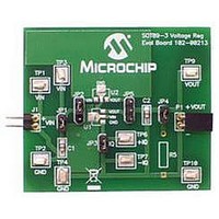
SOT89-3EV-VREG
Description
BOARD EVAL SOT89-3 VOLTAGE REG
Manufacturer
Microchip Technology
Datasheets
1.SOT89-3EV-VREG.pdf
(24 pages)
2.SOT89-3EV-VREG.pdf
(26 pages)
3.SOT89-3EV-VREG.pdf
(28 pages)
4.SOT89-3EV-VREG.pdf
(22 pages)
5.SOT89-3EV-VREG.pdf
(22 pages)
Specifications of SOT89-3EV-VREG
Channels Per Ic
1 - Single
Regulator Type
Positive Fixed
Board Type
Partially Populated
Utilized Ic / Part
SOT-89-3 Package
Silicon Manufacturer
Microchip
Application Sub Type
Voltage Regulator
Kit Application Type
Power Management - Voltage Regulator
Silicon Core Number
MCP1700A, MCP1701A, MCP1702, MCP1703
Lead Free Status / RoHS Status
Lead free / RoHS Compliant
Current - Output
-
Voltage - Output
-
Voltage - Input
-
Operating Temperature
-
Lead Free Status / Rohs Status
Lead free / RoHS Compliant


1.0
Absolute Maximum Ratings †
Input Voltage ........................................................+12V
Output Current (Continuous)..........P
Output Current (peak) ..................................... 500 mA
Output Voltage ............... (GND – 0.3V) to (V
Continuous Power Dissipation:
ELECTRICAL CHARACTERISTICS
© 2007 Microchip Technology Inc.
Electrical Specifications: Unless otherwise specified, all limits are established for an ambient temperature of T
Output Voltage Regulation
Maximum Output Current
Load Regulation (Note 3)
Dropout Voltage
Input Quiescent Current
Line Regulation
Input Voltage
Temperature Coefficient of
Output Voltage
Output Rise Time
3-Pin SOT-23A ............................................ 150 mW
3-Pin SOT-89............................................... 500 mW
3-Pin TO-92 ................................................. 300 mW
Parameters
1:
2:
3:
ELECTRICAL
CHARACTERISTICS
V
The input voltage V
TCV
over the temperature range. V
Load regulation is measured at a constant junction temperature using low duty cycle pulse testing.
R
is the nominal regulator output voltage. For example: V
OUT
= (V
OUT-HIGH
ΔV
V
ΔV
ΔV
TCV
I
IN
OUT/
OUT
Sym
V
IN
OUT
IN
V
- V
T
OUT
I
•V
Q
IN
R
= V
OUT
MAX
– V
V
•100
OUT
OUT
OUT
D
R
OUT-LOW
/(V
+ 1.0V, I
IN
V
OUT-LOW
-1.60
-2.25
-2.72
-3.00
-3.60
-1.60
R
– V
Min
250
200
150
150
125
110
—
—
—
—
—
—
—
—
—
—
—
IN
- 2%
) *10
OUT
+ 0.3V)
OUT
)mA
V
6
= Lowest voltage measured over the temperature range.
= 40 mA.
R
/ (V
±100
±0.8
±1.1
±1.3
±1.5
±1.8
±0.8
Typ
380
400
400
400
400
180
200
±0.5%
2.0
0.2
—
—
—
—
—
—
—
R
*
Δ
Temperature), V
V
R
+1.60
+2.25
+2.72
+3.00
+3.60
+1.60
† Notice: Stresses above those listed under “Absolute
Maximum Ratings” may cause permanent damage to the
device. These are stress ratings only and functional operation
of the device at these or any other conditions above those
indicated in the operation sections of the specifications is not
implied. Exposure to Absolute Maximum Rating conditions for
extended periods may affect device reliability.
Max
600
630
700
700
700
300
4.5
0.3
10
—
—
—
—
—
—
—
—
+ 2%
R
Units
= 1.8V, 2.5V, 3.3V, 4.0V, 5.0V.
ppm/
%/V
mA
mV
µA
°C
µs
V
%
V
OUT-HIGH
I
V
V
V
V
V
V
V
V
V
V
V
V
I
I
I
I
I
I
V
I
I
(Note 2)
10% V
R
OUT
OUT
OUT
OUT
OUT
OUT
OUT
OUT
OUT
OUT
OUT
OUT
OUT
OUT
OUT
OUT
OUT
OUT
OUT
OUT
OUT
IN
L
= 25Ω resistive
= V
= 40 mA (Note 1)
= 200 mA, V
= 200 mA, V
= 150 mA, V
= 150 mA, V
= 120 mA, V
= 20 mA, V
= 40 mA, (V
= 40 mA, -40°C ≤ T
= 5.0V
= 4.0V
= 3.3V
= 3.0V
= 2.5V
= 1.8V
= 5.0V, 1 mA ≤ I
= 4.0V, 1 mA ≤ I
= 3.3V, 1 mA ≤ I
= 3.0V, 1 mA ≤ I
= 2.5V, 1 mA ≤ I
= 1.8V, 1 mA ≤ I
R
R
= Highest voltage measured
to 90% V
+ 1.0V
MCP1701A
Conditions
(V
R
R
R
R
R
R
R
R
IN
= 1.8V
+1) ≤ V
, V
= 5.0V
= 4.0V
= 3.3V
= 3.0V
= 2.5V
= V
IN
OUT
OUT
OUT
OUT
OUT
OUT
A
R
DS21991C-page 3
A
= 0V to V
= +25°C.
+ 1.0V)
≤ +85°C
≤ 100 mA
≤ 100 mA
≤ 80 mA
≤ 80 mA
≤ 60 mA
≤ 30 mA
IN
≤ 10.0V
R
+1V,
Related parts for SOT89-3EV-VREG
Image
Part Number
Description
Manufacturer
Datasheet
Request
R

Part Number:
Description:
Manufacturer:
Infineon Technologies
Datasheet:
Part Number:
Description:
Manufacturer:
Infineon Technologies
Datasheet:
Part Number:
Description:
Manufacturer:
Infineon Technologies
Datasheet:
Part Number:
Description:
Manufacturer:
Infineon Technologies
Datasheet:
Part Number:
Description:
Manufacturer:
Infineon Technologies
Datasheet:
Part Number:
Description:
Manufacturer:
Infineon Technologies
Datasheet:
Part Number:
Description:
Manufacturer:
Infineon Technologies
Datasheet:
Part Number:
Description:
Manufacturer:
Infineon Technologies
Datasheet:
Part Number:
Description:
Manufacturer:
Infineon Technologies
Datasheet:
Part Number:
Description:
Manufacturer:
Infineon Technologies
Datasheet:
Part Number:
Description:
Manufacturer:
Infineon Technologies
Datasheet:
Part Number:
Description:
Manufacturer:
Infineon Technologies
Datasheet: