NCP5603GEVB ON Semiconductor, NCP5603GEVB Datasheet - Page 5
NCP5603GEVB
Manufacturer Part Number
NCP5603GEVB
Description
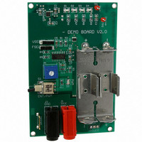
EVAL BOARD FOR NCP5603G HI FREQ
Manufacturer
ON Semiconductor
Specifications of NCP5603GEVB
Design Resources
NCP5603 EVB BOM NCP5603GEVB Gerber Files NCP5603 EVB Schematic
Current - Output / Channel
160mA
Outputs And Type
1, Non-Isolated
Voltage - Output
4.5 ~ 5 V
Features
Dimmable
Voltage - Input
3V or 3.6V
Utilized Ic / Part
NCP5603
Core Chip
NCP5603
Topology
Charge Pump
No. Of Outputs
1
Development Tool Type
Hardware - Eval/Demo Board
Leaded Process Compatible
Yes
Mcu Supported Families
NCP5603
Rohs Compliant
Yes
Lead Free Status / RoHS Status
Lead free / RoHS Compliant
For Use With/related Products
NCP5603G
Other names
NCP5603GEVBOS


assembled in a standard battery holder, the operating mode
being selected by the S1, S5 and S6 switches. Since the total
current is limited by the DC/DC converter, the backlights
LEDs are automatically deactivated when either the Torch
or the Flash are selected. Moreover, the Flash is not available
while the Torch is running.
switch S1 is associated with potentiometer P1. When the
switch is connected to ground, the NCP5603 enabling pin
EN is high and the brightness is maximized. When the
depicted Figure 4, and no uncontrolled current takes place
when the system starts up from scratch.
With a startup time well below 1 ms (from zero to full Vout,
see Figure 4), the NCP5603 is fast enough to accommodate a
flash application as shown in the demo board.
Table 2. Demo Board Efficiency
The system is powered by two AA cells in series,
An extra feature, backlight dimming, is provided by
The inrush current is internally limited by the chip, as
3.50 V
3.50 V
3.50 V
3.10 V
3.10 V
3.10 V
V
bat
Figure 4. Typical Startup Timing
132 mA
170 mA
131 mA
169 mA
300 mA
2.3 mA
I
bat
4.42 V
4.92 V
4.42 V
4.92 V
4.92 V
V
0 V
out
I
16.5 mA
21.4 mA
16.5 mA
21.4 mA
142 mA
out
0 mA
http://onsemi.com
/LED
AND8192/D
5
switch S1 is flipped to the Vcc position, the RESET of U5A
is released and the EN pin is clocked High / Low by the clock
generated by U2A / U2B. Simultaneously, diode LED D7
turns ON to identify the PWM mode of operation. The duty
cycle of the U5A / Q output is manually adjusted by
potentiometer P1 to set the brightness of the four associated
LED.
temperature (see Table 2), the results being fully within the
NCP5603 data sheet specifications.
Although there is no dedicated pin, the LED brightness can
be dimmed by means of the EN digital control. The
waveform captured in Figure 5 illustrate this behavior, the
PWM being intentionally arranged out of the audio band for
a portable system.
The efficiency of the system has been evaluated at room
I
85.6 mA
85.6 mA
out
142 mA
66 mA
66 mA
0 mA
Total
Figure 5. Typical Digital Dimming
63.14%
70.78%
71.83%
80.38%
75.12%
Yield
−
Torch operation
Comments
No Load
Related parts for NCP5603GEVB
Image
Part Number
Description
Manufacturer
Datasheet
Request
R

Part Number:
Description:
High Efficiency Charge Pump Converter
Manufacturer:
ON Semiconductor
Datasheet:
Part Number:
Description:
ON Semiconductor [VOLTAGE REGULATOR]
Manufacturer:
ON Semiconductor
Datasheet:
Part Number:
Description:
357-036-542-201 CARDEDGE 36POS DL .156 BLK LOPRO
Manufacturer:
ON Semiconductor
Datasheet:
Part Number:
Description:
357-036-542-201 CARDEDGE 36POS DL .156 BLK LOPRO
Manufacturer:
ON Semiconductor
Datasheet:
Part Number:
Description:
357-036-542-201 CARDEDGE 36POS DL .156 BLK LOPRO
Manufacturer:
ON Semiconductor
Datasheet:
Part Number:
Description:
357-036-542-201 CARDEDGE 36POS DL .156 BLK LOPRO
Manufacturer:
ON Semiconductor
Datasheet:
Part Number:
Description:
357-036-542-201 CARDEDGE 36POS DL .156 BLK LOPRO
Manufacturer:
ON Semiconductor
Datasheet:
Part Number:
Description:
357-036-542-201 CARDEDGE 36POS DL .156 BLK LOPRO
Manufacturer:
ON Semiconductor
Datasheet:
Part Number:
Description:
357-036-542-201 CARDEDGE 36POS DL .156 BLK LOPRO
Manufacturer:
ON Semiconductor
Datasheet:
Part Number:
Description:
357-036-542-201 CARDEDGE 36POS DL .156 BLK LOPRO
Manufacturer:
ON Semiconductor
Datasheet:
Part Number:
Description:
357-036-542-201 CARDEDGE 36POS DL .156 BLK LOPRO
Manufacturer:
ON Semiconductor
Datasheet:
Part Number:
Description:
357-036-542-201 CARDEDGE 36POS DL .156 BLK LOPRO
Manufacturer:
ON Semiconductor
Datasheet:
Part Number:
Description:
Manufacturer:
ON Semiconductor
Datasheet:
Part Number:
Description:
Manufacturer:
ON Semiconductor
Datasheet: