LP3944ISQEV National Semiconductor, LP3944ISQEV Datasheet - Page 2
LP3944ISQEV
Manufacturer Part Number
LP3944ISQEV
Description
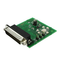
BOARD EVALUATION LP3944ISQ
Manufacturer
National Semiconductor
Series
PowerWise®r
Specifications of LP3944ISQEV
Current - Output / Channel
25mA
Outputs And Type
8, Non-Isolated
Features
Dimmable, I²C Interface
Voltage - Input
2.3 ~ 5.5 V
Utilized Ic / Part
LP3944
Core Chip
LP3944
No. Of Outputs
8
Output Current
25mA
Dimming Control Type
I2C
Kit Contents
Board, User Guide
Development Tool Type
Hardware - Eval/Demo Board
Lead Free Status / RoHS Status
Not applicable / Not applicable
Voltage - Output
-


www.national.com
Getting Started
Launching the software with the evaluation board
connected to the LPT cable:
1. Connect a power supply (typically 5V) to “V
The Control Panel
Individual LED settings — allows the user to program
LED0 to LED7 by turning it on or off or dimming/blinking at a
specified rate. DIM0 corresponds to the values programmed
in PWM0 and PSC0 registers. DIM1 corresponds to the
values programmed in PWM1 and PSC1 registers. The de-
fault state is off for all LEDs.
DIM0 — The sliding bars control the PSC0 and PWM0 reg-
isters. The PSC0 register is used to program the period of
DIM0 (6.25 ms to 1.6s). The PWM0 register is used to
program the duty cycle of DIM0 (0% to 100%). The default
values are 6.25 ms and 50% duty cycle.
DIM1 — The sliding bars control the PSC1 and PWM1 reg-
isters. The PSC1 register is used to program the period of
DIM1 (6.25 ms to 1.6s). The PWM1 register is used to
program the duty cycle of DIM1 (0% to 100%). The default
values are 6.25 ms and 50% duty cycle.
“GND” pins. Power supply’s negative terminal should be
connected to “GND” and positive to “V
provide power to the LP3944 and the LEDs. Jumper JP1
should be in the “V
separate power supply can be connected to “VEXT” to
supply power to LEDs, with jumper JP1 in the “VEXT”
position.
LP3944 software launched with evaluation board connected to LPT cable (in default state).
DD
” position. For added flexibility, a
(Continued)
DD
”. This will
DD
” and
2
2. The evaluation board is now ready for operation. Turn on
3. Connect the LPT cable to the evaluation board and the
4. Start the software by double-clicking on its icon.
5. The evaluation kit is now ready to use and the LP3944
Registers — This display shows the current status of the ten
registers (in hex) in the LP3944. Registers 00 and 01 are
read-only registers that can be updated by clicking on the
buttons. The other registers can be updated by clicking on
“Read All.”
COMM — Message indicating proper/improper I
nication. Upon successful communication, “Ack OK” with
green background will be displayed. Otherwise, “NoAck” with
red background will be displayed. Errors include absence of
power supply to the evaluation board, absence of LPT cable
connection, and wrong LPT port address.
LPT Base — Three options for LPT port setting. Default
value is 378.
Demos to screen — By selecting this option, the individual
LED settings panel will become active to reflect the states of
LEDs in demos.
the power supply.
LPT port of your PC.
can be programmed and controlled through the PC
software.
20127402
2
C commu-
Related parts for LP3944ISQEV
Image
Part Number
Description
Manufacturer
Datasheet
Request
R

Part Number:
Description:
National Semiconductor [8-Bit D/A Converter]
Manufacturer:
National Semiconductor
Datasheet:
Part Number:
Description:
National Semiconductor [Media Coprocessor]
Manufacturer:
National Semiconductor
Datasheet:
Part Number:
Description:
Digitally Controlled Tone and Volume Circuit with Stereo Audio Power Amplifier, Microphone Preamp Stage and National 3D Sound
Manufacturer:
National Semiconductor
Datasheet:
Part Number:
Description:
Digitally Controlled Tone and Volume Circuit with Stereo Audio Power Amplifier, Microphone Preamp Stage and National 3D Sound
Manufacturer:
National Semiconductor
Datasheet:
Part Number:
Description:
AC97 Rev 2 Codec with Sample Rate Conversion and National 3D Sound
Manufacturer:
National Semiconductor
Part Number:
Description:
Manufacturer:
National Semiconductor
Datasheet:
Part Number:
Description:
Manufacturer:
National Semiconductor
Datasheet:
Part Number:
Description:
General Purpose, Low Voltage, Low Power, Rail-to-Rail Output Operational Amplifiers
Manufacturer:
National Semiconductor
Datasheet:
Part Number:
Description:
8-bit 20 MSPS flash A/D converter.
Manufacturer:
National Semiconductor
Datasheet:
Part Number:
Description:
Low Noise Quad Operational Amplifier
Manufacturer:
National Semiconductor
Datasheet:
Part Number:
Description:
Quad Differential Line Receivers
Manufacturer:
National Semiconductor
Datasheet:
Part Number:
Description:
Quad High Speed Trapezoidal? Bus Transceiver
Manufacturer:
National Semiconductor
Datasheet:
Part Number:
Description:
Dual Line Receiver
Manufacturer:
National Semiconductor
Datasheet:
Part Number:
Description:
TTL to 10k ECL Level Translator with Latch
Manufacturer:
National Semiconductor
Datasheet: