LM3552SDEV National Semiconductor, LM3552SDEV Datasheet - Page 12
LM3552SDEV
Manufacturer Part Number
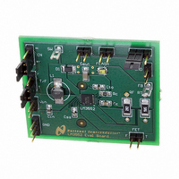
LM3552SDEV
Description
BOARD EVALUATION LM3552SD
Manufacturer
National Semiconductor
Series
PowerWise®r
Specifications of LM3552SDEV
Current - Output / Channel
700mA
Outputs And Type
1, Non-Isolated
Voltage - Output
4 V
Features
Flash Timeout Protection
Voltage - Input
2.7 ~ 5.5V
Utilized Ic / Part
LM3552
Core Chip
LM3552
Topology
Boost
No. Of Outputs
1
Output Current
1A
Input Voltage
2.7V To 5.5V
Development Tool Type
Hardware - Eval/Demo Board
Mcu Supported Families
LM3552
Lead Free Status / RoHS Status
Not applicable / Not applicable


www.national.com
where R
frequency, V
amplifier transconductance and R
on-resistance. The value for g
Electrical Characteristics table.
Right Half Plane Zero
A current mode control boost regulator has an inherent right
half plane zero (RHP zero). This zero has the effect of a zero
in the gain plot, causing an imposed +20dB/decade on the
rolloff, but has the effect of a pole in the phase, subtracting
another 90° in the phase plot. This can cause undesirable
effects if the control loop is influenced by this zero. To ensure
the RHP zero does not cause instability issues, the control
loop should be designed to have a bandwidth of less than ½
the frequency of the RHP zero. This zero occurs at a fre-
quency of:
where I
Compensation Components
The LM3551 and LM3552 provide a compensation pin (V
to customize the voltage loop feedback. It is recommended
that a series combination of R
pensation network, as shown in the typical application circuit.
For any given application, there exists a unique combination
of R
LM3551/2 circuit in terms of its transient response. The series
combination of R
frequency of the pole created is determined by the equation:
where R
proximately 900kΩ. Since R
R
glected until a value is chosen to set the zero f
to cancel the pole created by the output capacitor, f
output capacitor pole will shift with different load currents as
shown by the equation, so setting the zero is not exact. De-
termine the range of f
the zero f
quency of this zero is determined by:
Now R
to make sure that the pole f
range, and change each value slightly if needed to ensure
both component values are in the recommended range. For
both typical applications circuits shown on the front page, the
Recommended value for C
Lumiled applications. 10nF and 27kΩ are recommended
for Sharp applications.
O
, it has little effect on the above equation and can be ne-
C
C
and C
LOAD
L
O
can be chosen with the selected value for C
ZC
is the minimum load resistance, fs is the switching
is the output impedance of the error amplifier, ap-
is the maximum load current.
to a point approximately in the middle. The fre-
IN
C
is the minimum input voltage, g
that will optimize the performance of the
C
and C
P1
over the expected loads and then set
C
introduces a pole-zero pair. The
PC
C
C
m
C
is 4.7nF and R
is generally much less than
and R
and C
is still in the 10Hz to 500Hz
DSON-S
DSON-S
C
be used for the com-
is the power switch
ZC
are found in the
. f
C
m
ZC
= 10kΩ for
is the error
is created
C
. Check
P1
. The
C
)
12
RECOMMENDED MINIMUM COMPONENT
SPECIFICATIONS
Torch and Flash Resistor ratings are dependent upon the
current through each resistor. The minimum ratings will vary
depending upon the current selected on an applicaiton by ap-
plication basis. Power Rating Minimum = (Desired Current)
× Resistor Value. See the CURRENT SET EQUATIONS sec-
tion to determine torch and flash currents.
THERMAL PROTECTION
Internal thermal protection circuitry disables the LM3551/2
when the junction temperature exceeds +140°C (typ.). This
feature protects the device from being damaged by high die
temperatures that might otherwise result from excessive pow-
er dissipation. The device will recover and operate normally
when the junction temperature falls below +120°C (typ.). It is
important that the board layout provide good thermal conduc-
tion to keep the junction temperature within the specified
operating ratings.
PCB LAYOUT CONSIDERATIONS
The LLP is a leadframe based Chip Scale Package (CSP)
with very good thermal properties. This package has an ex-
posed DAP (die attach pad) at the center of the package
measuring 2.6mm x 3.0mm. The main advantage of this ex-
posed DAP is to offer lower thermal resistance when it is
soldered to the thermal land pad on the PCB. For PCB layout,
National highly recommends a 1:1 ratio between the package
and the PCB thermal land. To further enhance thermal con-
ductivity, the PCB thermal land may include vias to a ground
plane. For more detailed instructions on mounting LLP pack-
ages, please refer to National Semiconductor Application
Note AN-1187.
Component
R
R
C
C
TORCH
C
FLASH
C
C
R
L1
OUT
FTO
SS
IN
C
C
10µF (Lumiled)
10uF (Lumiled)
4.7µF (Sharp)
4.7µF (Sharp)
Determined
Determined
Determined
Determined
(Lumiled)
(Lumiled)
(Sharp)
(Sharp)
Value
4.7µH
4.7nF
10nF
10kΩ
27kΩ
User
User
User
User
10V X5R or X7R
16V X5R or X7R
2.0A 30% I
6.3V X5R or
6.3V X5R or
6.3V X5R or
Application
Application
Ratings
Specific
Specific
Rating
X7R
X7R
X7R
SAT
2
Related parts for LM3552SDEV
Image
Part Number
Description
Manufacturer
Datasheet
Request
R


Part Number:
Description:
Precision Centigrade Temperature Sensors
Manufacturer:
National Semiconductor

Part Number:
Description:
Precision Centigrade Temperature Sensors
Manufacturer:
National Semiconductor Corporation
Datasheet:
Part Number:
Description:
National Semiconductor [8-Bit D/A Converter]
Manufacturer:
National Semiconductor
Datasheet:
Part Number:
Description:
National Semiconductor [Media Coprocessor]
Manufacturer:
National Semiconductor
Datasheet:
Part Number:
Description:
Digitally Controlled Tone and Volume Circuit with Stereo Audio Power Amplifier, Microphone Preamp Stage and National 3D Sound
Manufacturer:
National Semiconductor
Datasheet:
Part Number:
Description:
Digitally Controlled Tone and Volume Circuit with Stereo Audio Power Amplifier, Microphone Preamp Stage and National 3D Sound
Manufacturer:
National Semiconductor
Datasheet:
Part Number:
Description:
AC97 Rev 2 Codec with Sample Rate Conversion and National 3D Sound
Manufacturer:
National Semiconductor
Part Number:
Description:
Manufacturer:
National Semiconductor
Datasheet:
Part Number:
Description:
Manufacturer:
National Semiconductor
Datasheet:
Part Number:
Description:
General Purpose, Low Voltage, Low Power, Rail-to-Rail Output Operational Amplifiers
Manufacturer:
National Semiconductor
Datasheet:
Part Number:
Description:
8-bit 20 MSPS flash A/D converter.
Manufacturer:
National Semiconductor
Datasheet:
Part Number:
Description:
Low Noise Quad Operational Amplifier
Manufacturer:
National Semiconductor
Datasheet:
Part Number:
Description:
Quad Differential Line Receivers
Manufacturer:
National Semiconductor
Datasheet: