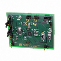
LM3552SDEV National Semiconductor, LM3552SDEV Datasheet - Page 3

LM3552SDEV
Manufacturer Part Number
LM3552SDEV
Description
BOARD EVALUATION LM3552SD
Manufacturer
National Semiconductor
Series
PowerWise®r
Specifications of LM3552SDEV
Current - Output / Channel
700mA
Outputs And Type
1, Non-Isolated
Voltage - Output
4 V
Features
Flash Timeout Protection
Voltage - Input
2.7 ~ 5.5V
Utilized Ic / Part
LM3552
Core Chip
LM3552
Topology
Boost
No. Of Outputs
1
Output Current
1A
Input Voltage
2.7V To 5.5V
Development Tool Type
Hardware - Eval/Demo Board
Mcu Supported Families
LM3552
Lead Free Status / RoHS Status
Not applicable / Not applicable
National does not assume any responsibility for use of any circuitry described, no circuit patent licenses are implied and National reserves
the right at any time without notice to change said circuitry and specifications.
For the most current product information visit us at www.national.com.
LIFE SUPPORT POLICY
NATIONAL’S PRODUCTS ARE NOT AUTHORIZED FOR USE AS CRITICAL COMPONENTS IN LIFE SUPPORT DEVICES OR SYSTEMS
WITHOUT THE EXPRESS WRITTEN APPROVAL OF THE PRESIDENT AND GENERAL COUNSEL OF NATIONAL SEMICONDUCTOR
CORPORATION. As used herein:
1. Life support devices or systems are devices or systems
BANNED SUBSTANCE COMPLIANCE
National Semiconductor follows the provisions of the Product Stewardship Guide for Customers (CSP-9-111C2) and Banned Substances
and Materials of Interest Specification (CSP-9-111S2) for regulatory environmental compliance. Details may be found at:
www.national.com/quality/green.
Lead free products are RoHS compliant.
Board Operation
BASIC CONNECTIONS
To operate the LM3552 White LED Flash Driver Evaluation
Board, connect a supply voltage (2.7V-5.5V) between board
connectors VIN and GND.
Default Jumper Connections:
When these connections are all made correctly, the Flash
LED will be OFF. Setting the EN jumper to the ON position
www.national.com
•
• T/F: Connects the “T” post to the middle post of the T/F
which, (a) are intended for surgical implant into the body, or
(b) support or sustain life, and whose failure to perform when
properly used in accordance with instructions for use
provided in the labeling, can be reasonably expected to result
in a significant injury to the user.
EN header strip. This connects GND to the EN pin of the
LM3552, disabling the part.
header strip. This connects GND to the T/F pin of the
LM3552, placing the part into the 200mA torch mode
when the part is enabled
EN: Connects the “OFF” post to the middle post of the
National Semiconductor
Americas Customer
Support Center
Email: new.feedback@nsc.com
Tel: 1-800-272-9959
National Semiconductor
Europe Customer Support Center
Deutsch Tel: +49 (0) 69 9508 6208
English
Français Tel: +33 (0) 1 41 91 8790
Email: europe.support@nsc.com
Fax: +49 (0) 180-530 85 86
Tel: +44 (0) 870 24 0 2171
2. A critical component is any component of a life support device
will enable the part and turn on the flash LED. In torch mode,
the LED current will be set to approximately 200mA. Placing
the the T/F jumper across the ’+’ pin and the T/F pin enables
flash mode. The total current delivered to the LED is approxi-
mately 700mA. If this jumper is left in flash mode, the internal
time-out circuit will disable the switcher after approximately 1
second.
The EN pin has an internal pull-down resistor placing the
part in shutdown by default. The T/F pin does not have a
pull-up or pull-down resistor. If left unconnected, it is un-
known as to whether the LM3552 is in torch or flash mode.
For more information regarding the operation of the
LM3551/2, please refer to the LM3551/2 datasheet.
or system whose failure to perform can be reasonably
expected to cause the failure of the life support device or
system, or to affect its safety or effectiveness.
National Semiconductor
Asia Pacific Customer
Support Center
Email: ap.support@nsc.com
National Semiconductor
Japan Customer Support Center
Fax: 81-3-5639-7507
Email: jpn.feedback@nsc.com
Tel: 81-3-5639-7560


