LM3424BKBSTEVAL/NOPB National Semiconductor, LM3424BKBSTEVAL/NOPB Datasheet - Page 8
LM3424BKBSTEVAL/NOPB
Manufacturer Part Number
LM3424BKBSTEVAL/NOPB
Description
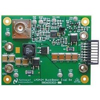
BOARD EVAL BUCK BOOST LM3424
Manufacturer
National Semiconductor
Series
PowerWise®r
Specifications of LM3424BKBSTEVAL/NOPB
Current - Output / Channel
1A
Outputs And Type
1, Non-Isolated
Features
Dimmable
Voltage - Input
10 ~ 70 V
Utilized Ic / Part
LM3424
Core Chip
LM3424
Topology
Buck-Boost
No. Of Outputs
1
Dimming Control Type
PWM / Analog
Development Tool Type
Hardware - Eval/Demo Board
Mcu Supported Families
LM3424 Family
Lead Free Status / RoHS Status
Lead free / RoHS Compliant
Voltage - Output
-
Other names
LM3424BKBSTEVAL


www.national.com
Assume R
The chosen components from step 9 are:
10. INPUT CAPACITANCE
Solve for the minimum C
To minimize power supply interaction a 200% larger capaci-
tance of approximately 20 µF is used, therefore the actual
Δv
selection is limited, four 4.7 µF X7R capacitors are chosen.
Determine minimum allowable RMS current rating:
The chosen components from step 10 are:
11. NFET
Determine minimum Q1 voltage rating and current rating:
A 100V NFET is chosen with a current rating of 32A due to
the low R
The chosen component from step 11 is:
IN-PP
is much lower. Since high voltage ceramic capacitor
DS-ON
FS
= 10Ω and solve for C
= 50 mΩ. Determine I
IN
:
FS
T-RMS
:
and P
T
:
8
12. DIODE
Determine minimum D1 voltage rating and current rating:
A 100V diode is chosen with a current rating of 12A and V
600 mV. Determine P
The chosen component from step 12 is:
13. INPUT UVLO
Solve for R
The closest standard resistor is 150 kΩ therefore V
Solve for R
The closest standard resistor is 21 kΩ making V
The chosen components from step 13 are:
UV2
UV1
:
:
D
:
TURN-ON
HYS
is:
:
D
=
Related parts for LM3424BKBSTEVAL/NOPB
Image
Part Number
Description
Manufacturer
Datasheet
Request
R

Part Number:
Description:
National Semiconductor [8-Bit D/A Converter]
Manufacturer:
National Semiconductor
Datasheet:
Part Number:
Description:
National Semiconductor [Media Coprocessor]
Manufacturer:
National Semiconductor
Datasheet:
Part Number:
Description:
Digitally Controlled Tone and Volume Circuit with Stereo Audio Power Amplifier, Microphone Preamp Stage and National 3D Sound
Manufacturer:
National Semiconductor
Datasheet:
Part Number:
Description:
Digitally Controlled Tone and Volume Circuit with Stereo Audio Power Amplifier, Microphone Preamp Stage and National 3D Sound
Manufacturer:
National Semiconductor
Datasheet:
Part Number:
Description:
AC97 Rev 2 Codec with Sample Rate Conversion and National 3D Sound
Manufacturer:
National Semiconductor
Part Number:
Description:
Manufacturer:
National Semiconductor
Datasheet:
Part Number:
Description:
Manufacturer:
National Semiconductor
Datasheet:
Part Number:
Description:
General Purpose, Low Voltage, Low Power, Rail-to-Rail Output Operational Amplifiers
Manufacturer:
National Semiconductor
Datasheet:
Part Number:
Description:
8-bit 20 MSPS flash A/D converter.
Manufacturer:
National Semiconductor
Datasheet:
Part Number:
Description:
Low Noise Quad Operational Amplifier
Manufacturer:
National Semiconductor
Datasheet:
Part Number:
Description:
Quad Differential Line Receivers
Manufacturer:
National Semiconductor
Datasheet:
Part Number:
Description:
Quad High Speed Trapezoidal? Bus Transceiver
Manufacturer:
National Semiconductor
Datasheet:
Part Number:
Description:
Dual Line Receiver
Manufacturer:
National Semiconductor
Datasheet:
Part Number:
Description:
TTL to 10k ECL Level Translator with Latch
Manufacturer:
National Semiconductor
Datasheet: