LM3429BKBSTEVAL/NOPB National Semiconductor, LM3429BKBSTEVAL/NOPB Datasheet - Page 6
LM3429BKBSTEVAL/NOPB
Manufacturer Part Number
LM3429BKBSTEVAL/NOPB
Description
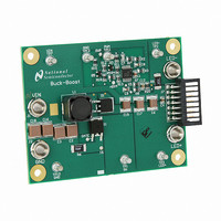
BOARD EVAL FOR BUCK-BOOST LM3429
Manufacturer
National Semiconductor
Series
PowerWise®r
Specifications of LM3429BKBSTEVAL/NOPB
Current - Output / Channel
1A
Outputs And Type
1, Non-Isolated
Features
Dimmable
Voltage - Input
10 ~ 70 V
Utilized Ic / Part
LM3429
Core Chip
LM3429
Topology
Buck-Boost
No. Of Outputs
1
Dimming Control Type
PWM / Analog
Development Tool Type
Hardware - Eval/Demo Board
Mcu Supported Families
LM3429 Family
Lead Free Status / RoHS Status
Lead free by exemption / RoHS compliant by exemption
Voltage - Output
-
Other names
*LM3429BKBSTEVAL
*LM3429BKBSTEVAL/NOPB
LM3429BKBSTEVAL
*LM3429BKBSTEVAL/NOPB
LM3429BKBSTEVAL


www.national.com
5. OUTPUT CAPACITANCE
Solve for C
A total value of 6.6 µF (using 3 2.2 µF X7R ceramic capaci-
tors) is chosen therefore the actual Δi
Determine minimum allowable RMS current rating:
The chosen components from step 5 are:
6. PEAK CURRENT LIMIT
Solve for R6:
The closest standard resistor is 0.05 Ω therefore I
The chosen component from step 6 is:
7. LOOP COMPENSATION
ω
ω
P1
Z1
is approximated:
is approximated:
O
:
LED-PP
is:
LIM
is:
6
T
To ensure stability, calculate ω
Solve for C8:
Since PWM dimming can be evaluated with this board, a
much larger compensation capacitor C8 = 1.0 µF is chosen.
To attenuate switching noise, calculate ω
Assume R20 = 10Ω and solve for C12:
The chosen components from step 7 are:
8. INPUT CAPACITANCE
Solve for the minimum C
To minimize power supply interaction a 3x larger capacitance
of approximately 20 µF is used, therefore the actual Δv
is much lower. Since high voltage ceramic capacitor selection
is limited, four 4.7 µF X7R capacitors are chosen.
Determine minimum allowable RMS current rating:
The chosen components from step 8 are:
U0
is approximated:
IN
:
P2
:
P3
:
IN-PP
Related parts for LM3429BKBSTEVAL/NOPB
Image
Part Number
Description
Manufacturer
Datasheet
Request
R

Part Number:
Description:
National Semiconductor [8-Bit D/A Converter]
Manufacturer:
National Semiconductor
Datasheet:
Part Number:
Description:
National Semiconductor [Media Coprocessor]
Manufacturer:
National Semiconductor
Datasheet:
Part Number:
Description:
Digitally Controlled Tone and Volume Circuit with Stereo Audio Power Amplifier, Microphone Preamp Stage and National 3D Sound
Manufacturer:
National Semiconductor
Datasheet:
Part Number:
Description:
Digitally Controlled Tone and Volume Circuit with Stereo Audio Power Amplifier, Microphone Preamp Stage and National 3D Sound
Manufacturer:
National Semiconductor
Datasheet:
Part Number:
Description:
AC97 Rev 2 Codec with Sample Rate Conversion and National 3D Sound
Manufacturer:
National Semiconductor
Part Number:
Description:
Manufacturer:
National Semiconductor
Datasheet:
Part Number:
Description:
Manufacturer:
National Semiconductor
Datasheet:
Part Number:
Description:
General Purpose, Low Voltage, Low Power, Rail-to-Rail Output Operational Amplifiers
Manufacturer:
National Semiconductor
Datasheet:
Part Number:
Description:
8-bit 20 MSPS flash A/D converter.
Manufacturer:
National Semiconductor
Datasheet:
Part Number:
Description:
Low Noise Quad Operational Amplifier
Manufacturer:
National Semiconductor
Datasheet:
Part Number:
Description:
Quad Differential Line Receivers
Manufacturer:
National Semiconductor
Datasheet:
Part Number:
Description:
Quad High Speed Trapezoidal? Bus Transceiver
Manufacturer:
National Semiconductor
Datasheet:
Part Number:
Description:
Dual Line Receiver
Manufacturer:
National Semiconductor
Datasheet:
Part Number:
Description:
TTL to 10k ECL Level Translator with Latch
Manufacturer:
National Semiconductor
Datasheet: